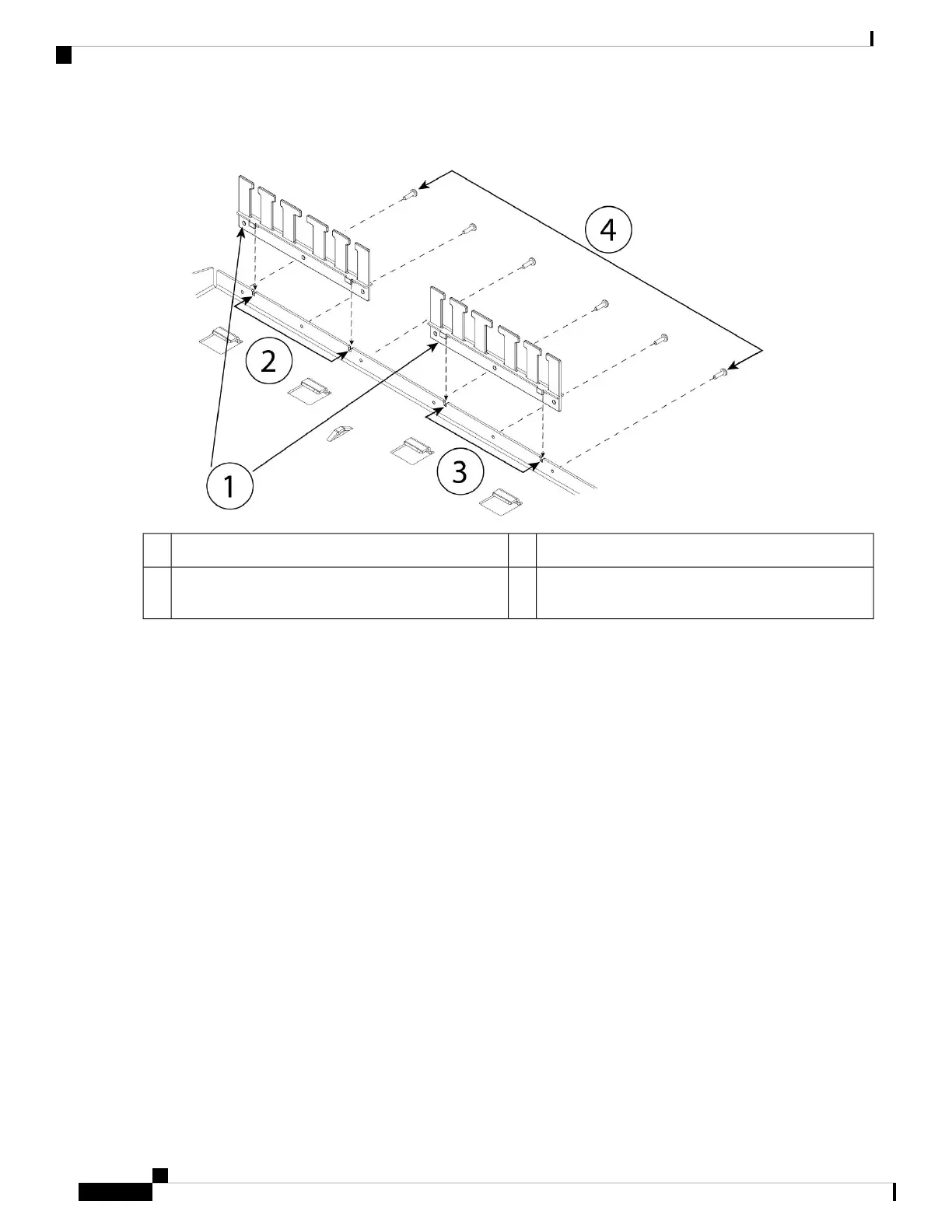
Figure 28: Attach the Cable Guides to the Rack Shelf Flange
Left cable guide rack shelf cutouts2Two cable guides (part number 700-122664-01)1
Six of the twelve Phillips M3 x 7-mm screws (part
number 48-1921-01)
4Right cable guide rack shelf cutouts3
a) Align the cable guides with the cutouts on the rack shelf flange (see figure above).
b) At the rear of the rack shelf, attach the left and right cable guides using six of the twelve Phillips M3 x 7-mm screws
(part number 48-1921-01).
Drive the screws in while facing the back of the rack shelf.
Note
c) Set the rack shelf aside. Continue with Step 2 to install the sliding rack tray on the chassis.
The figure in Step 8 shows the rack shelf with the cable guides attached.
Step 2 Place the chassis with the top facing down on a large, stable work area.
Step 3 Invert the sliding rack tray and position it on the chassis. You can mount the chassis with the front or rear panel facing
front.
Cisco Firepower 1010 Series Hardware Installation Guide
36
Mount the Chassis
Rack-Mount the Chassis

 Loading...