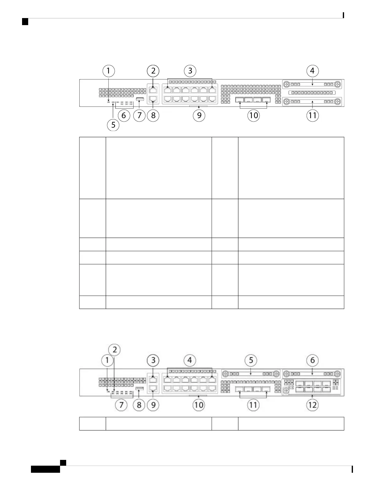
Figure 6: Firepower 2110 and 2120 Front Panel
Gigabit Ethernet management port:
• Firepower Threat
Defense—Management 0 (also
referred to as Management 1/1 and
Diagnostic 1/1)
• ASA—Management 1/1
2Power LED1
SSD 1 (slot 1)412 RJ-45 1 G/100 M/10 M auto
duplex/auto MDI-X Base-T ports
Ethernet 1/1 through 1/12 labeled top to
bottom, left to right
3
System LEDs6Locator beacon5
RJ-45 console port8Type A USB 2.0 port7
4 fixed SFP (1 G) ports
Fiber ports 1/13 through 1/16 labeled left
to right
10Pullout asset card with chassis serial
number
9
SSD (slot 2)11
The following figure shows the front panel of the Firepower 2130 and 2140. See Front Panel LEDs, on page
10 for a description of the LEDs.
Figure 7: Firepower 2130 and 2140 Front Panel
Locator beacon2Power LED1
Cisco Firepower 2100 Series Hardware Installation Guide
8
Overview
Front Panel
 Loading...


