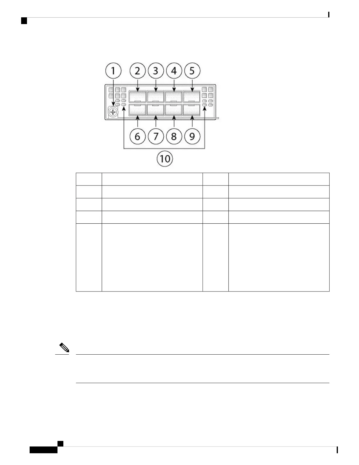
Figure 12: FPR2K-NM-8X10G
Ethernet X/1
2Captive screw/handle1
Ethernet X/5
4
Ethernet X/3
3
Ethernet X/2
6
Ethernet X/7
5
Ethernet X/6
8
Ethernet X/4
7
Network activity LEDs
• Off—No connection or port is not in
use.
• Amber—No link or network failure.
• Green—Link up.
• Green, flashing—Network activity.
10
Ethernet X/8
9
1-G Network Module
The following figure shows the front panel of the 1-G network module (FPR2K-NM-8X1G). The
FPR2K-NM-8X1G is a single-wide module that supports hot swapping. The eight ports are numbered from
top to bottom, left to right.
You can fit four copper SFPs in either the top row of ports or the bottom row of ports. Both rows cannot be
populated at the same time, because of the port row spacing. For a list of copper SFPS, see Supported SFP/SFP+
and QSFP Transceivers.
Note
Cisco Firepower 2100 Series Hardware Installation Guide
18
Overview
1-G Network Module
 Loading...


