EasyManuals Logo

Cisco Firepower 2110 Hardware Installation Guide

Cisco Firepower 2110
84 pages
To Next Page IconTo Next Page
To Previous Page IconTo Previous Page
Page #80 background imageLoading...
Page #80 background image
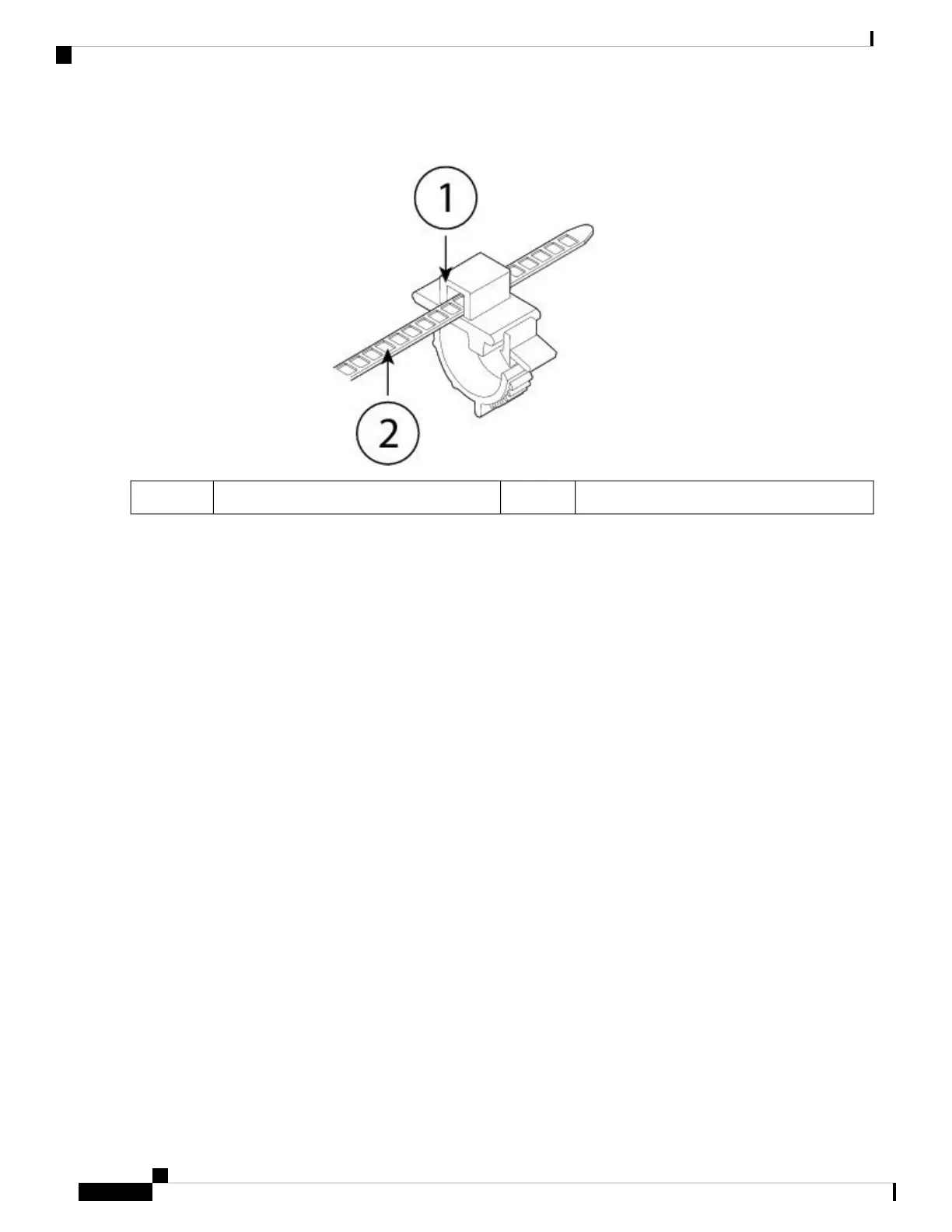
Figure 52: Tie Wrap Through the Box Channel of the Clamp
Tie wrap2Box channel1
Step 2 Attach the clamp to the power supply module:
a) Locate the hexagonal ventilation hole on the power supply module at the center of the plug just below the power
connector body (see the following figures).
b) Plug the snapping portion of the tie wrap into the hexagonal hole.
c) With the clamp side facing up, push the tie wrap in until it is fully engaged.
Make sure you have the correct location because you cannot remove the tie wrap from the power supply
module once you have installed it without damaging the tie wrap.
Caution
Cisco Firepower 2100 Series Hardware Installation Guide
76
Maintenance and Upgrade
Secure the Power Cord on the Power Supply Module

Other manuals for Cisco Firepower 2110

Questions and Answers:

Question and Answer IconNeed help?

Do you have a question about the Cisco Firepower 2110 and is the answer not in the manual?

Cisco Firepower 2110 Specifications

General IconGeneral
Rack Units1 RU
Operating Temperature32°F to 104°F (0°C to 40°C)
Humidity10% to 90% non-condensing
Maximum Concurrent Sessions2, 000, 000
AVC Throughput2.2 Gbps
Interfaces8 x 1G, 2 x 10G SFP+
Power SupplyAC
Dimensions (H x W x D)1.72 x 17.3 x 16.5 in
Storage Temperature-4°F to 149°F (-20°C to 65°C)

Related product manuals