EasyManuals Logo

Cisco Firepower 2110 Hardware Installation Guide

Cisco Firepower 2110
84 pages
To Next Page IconTo Next Page
To Previous Page IconTo Previous Page
Page #83 background imageLoading...
Page #83 background image
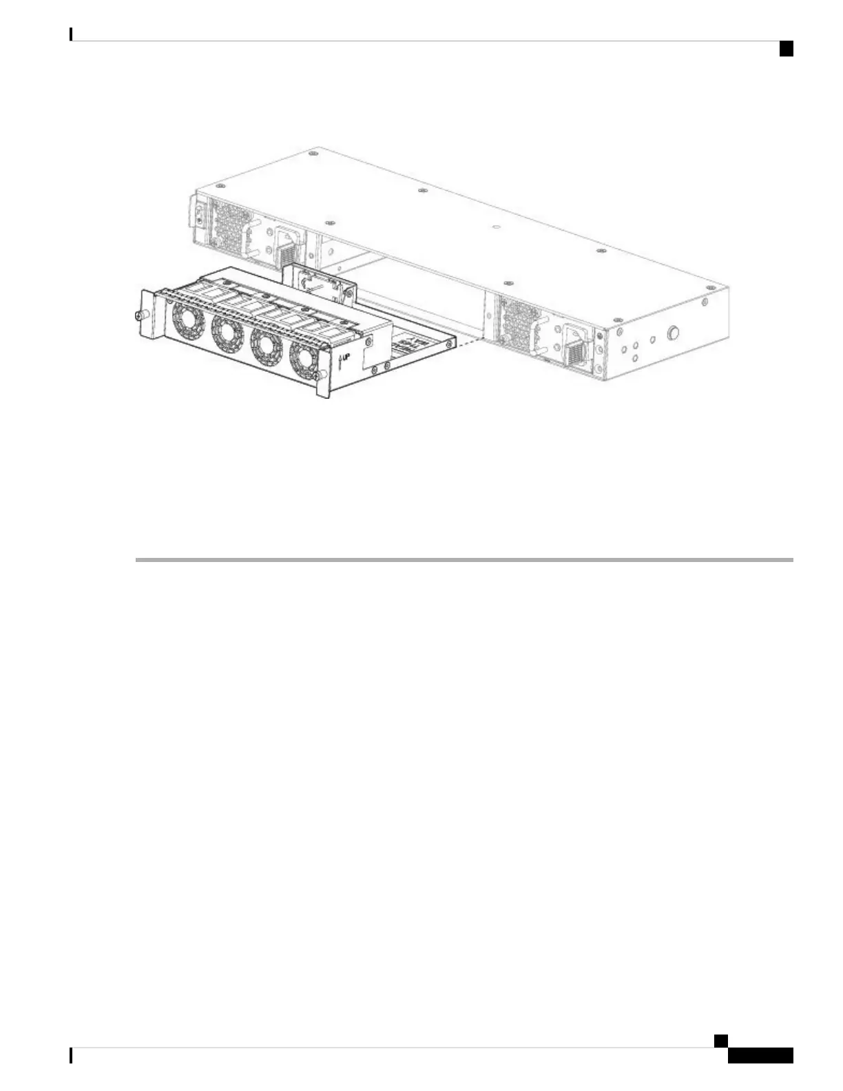
Figure 55: Remove the Fan Tray
Step 4 To replace a fan tray, hold the fan tray in front of the fan slot.
Step 5 Push the fan tray into the chassis until it is properly seated.
If the system is powered on, listen for the fans. You should immediately hear the fans operating. If you do not hear the
fans, make sure the fan tray is inserted completely into the chassis and the faceplate is flush with the outside surface of
the chassis.
Step 6 Verify that the fan is operational by checking the fan tray LED. See Front Panel LEDs, on page 10 for a description of
the fan LEDs.
Cisco Firepower 2100 Series Hardware Installation Guide
79
Maintenance and Upgrade
Remove and Replace the Fan Tray

Other manuals for Cisco Firepower 2110

Questions and Answers:

Question and Answer IconNeed help?

Do you have a question about the Cisco Firepower 2110 and is the answer not in the manual?

Cisco Firepower 2110 Specifications

General IconGeneral
Rack Units1 RU
Operating Temperature32°F to 104°F (0°C to 40°C)
Humidity10% to 90% non-condensing
Maximum Concurrent Sessions2, 000, 000
AVC Throughput2.2 Gbps
Interfaces8 x 1G, 2 x 10G SFP+
Power SupplyAC
Dimensions (H x W x D)1.72 x 17.3 x 16.5 in
Storage Temperature-4°F to 149°F (-20°C to 65°C)

Related product manuals