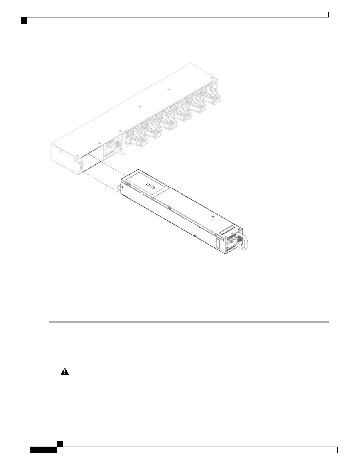
Figure 4: Remove the Power Supply Module
If the slot is to remain empty, install a blank faceplate to ensure proper airflow and to keep dust out of the chassis;
otherwise, install another power supply module.
Step 4 To replace a power supply module, hold the power supply module with both hands and slide it into the power supply
module bay.
Step 5 Push in the power supply module gently until you hear the latch engage and it is seated. Verify the power supply module
is operating correctly by checking the power supply module LED. See Power Supply Modules for a description of the
power supply module LEDs.
Connect the DC Power Supply Module
Take note of the following warnings:
Statement 1002—DC Power Supply
When stranded wiring is required, use approved wiring terminations, such as closed-loop or spade-type with
upturned lugs. These terminations should be the appropriate size for the wires and should clamp both the
insulation and conductor.
Warning
Maintenance and Upgrade
10
Maintenance and Upgrade
Connect the DC Power Supply Module
 Loading...


