1-Gb Network Module with Hardware Bypass
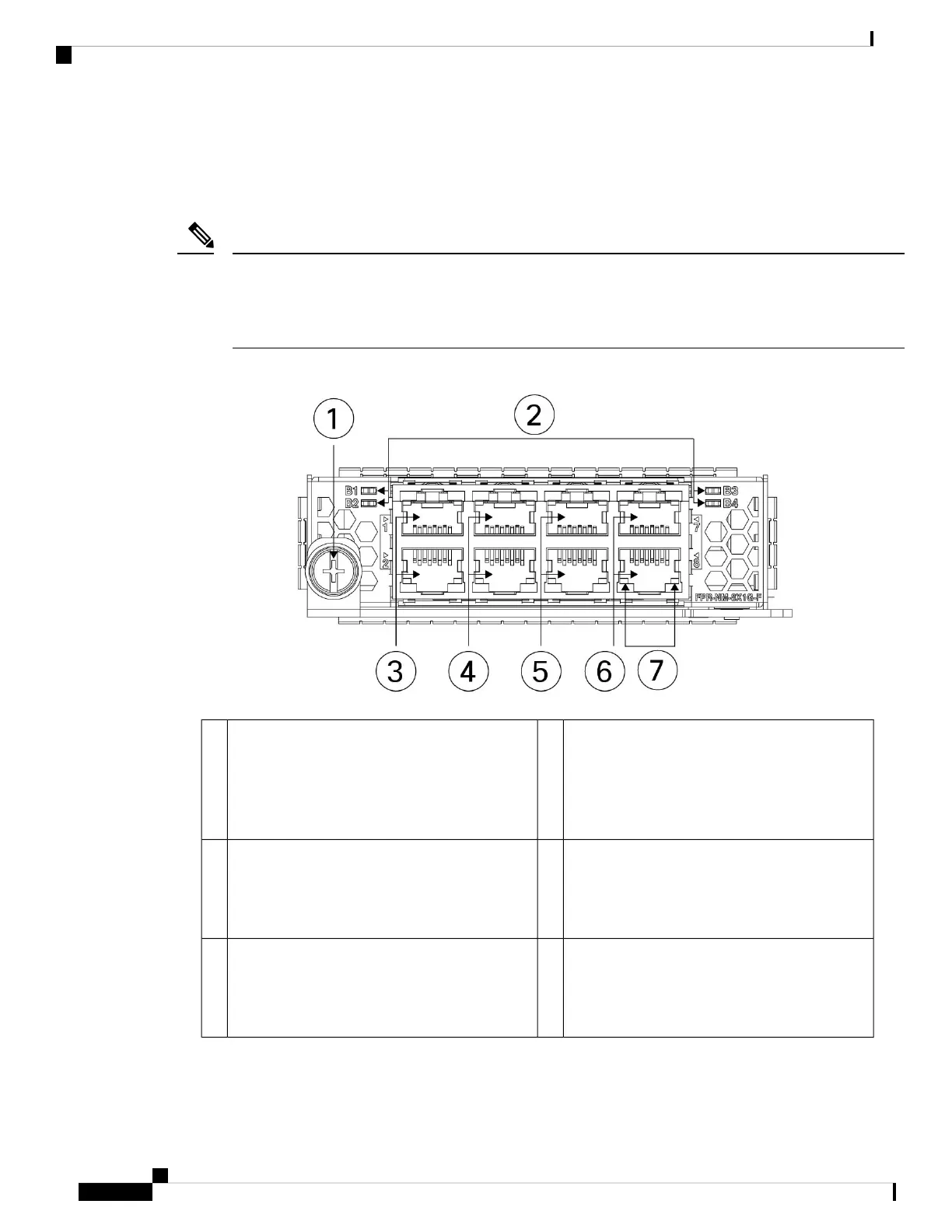
The following figure shows the front panel view of the 1-Gb network module with hardware bypass
(FPR-NM-8X1G-F). Pair ports 1 and 2, 3 and 4, 5 and 6, and 7 and 8 to form hardware bypass paired sets.
Make sure you have the correct firmware package and software version installed to support this network
module. For instructions on how to verify your firmware package version and to upgrade the firmware if
necessary, see the Cisco Firepower 4100/9300 FXOS Firmware Upgrade Guide. See Cisco Firepower 4100/9300
FXOS Compatibility for the software compatibility matrix.
Note
Figure 12: FPR-NM-8X1G-F
Bypass LEDs B1 through B4
• Green—In standby mode.
• Amber, flashing—Port is in hardware bypass
mode, failure event.
2Captive screw/handle1
Ethernet X/2
Ports 3 and 4 are paired together to form a
hardware bypass pair. LED B2 applies to this
paired port.
4Ethernet X/1
Ports 1 and 2 are paired together to form a
hardware bypass pair. LED B1 applies to this
paired port.
3
Ethernet X/2
Ports 7 and 8 are paired together to form a
hardware bypass pair. LED B4 applies to this
paired port.
6Ethernet X/2
Ports 5 and 6 are paired together to form a
hardware bypass pair. LED B3 applies to this
paired port.
5
Overview
18
Overview
1-Gb Network Module with Hardware Bypass
 Loading...


