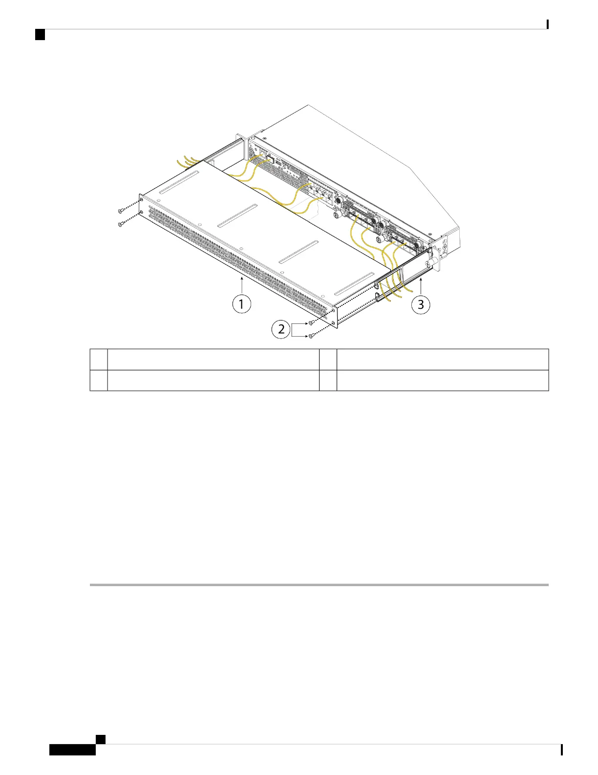
Figure 18: Attach the FIPS Opacity Shield to the Cable Management Brackets
8-32 x 0.375-inch Phillips screws (two per side)2FIPS opacity shield1
Cable management bracket3
Step 8 Attach the 15 TELs. For information on the procedure and correct placement of the TELs, see the Tamper Evidence
Label (TEL) Placement section (section 2.13 ) in the FIPS 140-2 Non Proprietary Security Policy Level 2 Validation
document.
Step 9 Attach the power cable to the chassis and connect it to an electrical outlet.
Step 10 Press the power switch on the rear panel.
Step 11 Check the power LED on the front panel. See Front Panel LEDs for a description of the power LED. Solid green
indicates that the chassis is powered on.
When you toggle the power switch from ON to OFF, it takes several seconds for the system to power down.
Do not remove the power cable until the power LED is off. After removing power from the chassis either by
moving the power switch to OFF or unplugging the power cord, wait at least 10 seconds before turning power
back ON.
Note
Step 12 See the Cisco Firepower 4100 Getting Started Guide for further configuration information.
Installation, Maintenance, and Upgrade
26
Installation, Maintenance, and Upgrade
Install the FIPS Opacity Shield
 Loading...


