9
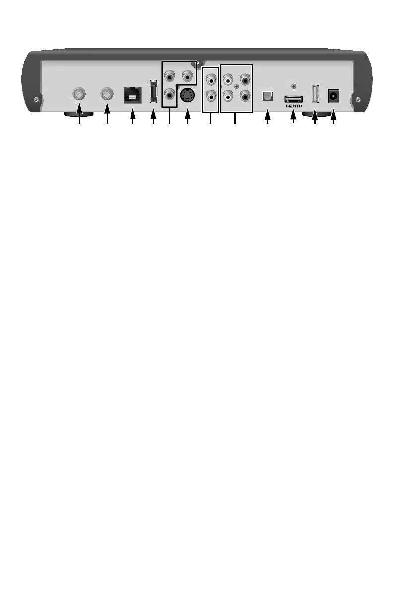
Back Panel
1 To Wall (Video In) Connect the set-top to in-house coaxial wiring, if applicable. (optional)
2 To TV (Video Out) Connect to TV. You must set the channel on your TV to the channel
designated by your service provider (usually channel 3). Contact your
service provider for the channel information (optional)
3 Network Connect to the Ethernet (CAT-5) network at your home, if applicable
4 eSATA Port Connect external SATA equipment approved by your service provider
to this port (optional)
5 YPbPr Connect the set-top to the component video input (YPbPr) on your
HDTV or SDTV. See pages 15 and 16 for more information
6 S-Video Connect an S-Video cable to send an S-Video signal to your TV, VCR, or
DVD recorder. This signal is standard-de nition but higher quality than
other standard-de nition TV connections. See page 17 for more
information (optional)
7 Video Out Connect to composite input on your HDTV or SDTV
Note: Two video output connectors are provided. Typically, one output
is connected to the TV, and the other output is used to connect to a
home theater system, DVD recorder, or VCR
8 Audio Out (L/R) Connect RCA-type cables to Audio Out to send analog audio signals
(left and right) to a TV with stereo inputs or to a stereo ampli er.
Note: Two sets of audio out connectors are provided. Typically, one set
of outputs is connected to the TV, and the other set is used to connect
to a home theater system, DVD recorder, VCR, or wireless headphones
9 Optical Connect an optical cable to send a digital audio signal to a surround-
sound system or other digital audio device
10 HDMI Connect an HDTV HDMI
™
(High-De nition Multimedia Interface) cable
from the HDTV to the HDMI port. HDMI supports both digital audio and
video. See page 15 for more information
11 USB Port Connects to external USB equipment approved by your service
provider (optional)
12 Power Connect the DC output of the AC power adapter (provided) to deliver
power to the set-top. Use only the AC power adapter provided with
the set-top
Note: This illustration may vary from the actual product.
T14256
Pb Y
Pr
VIDEO
OUT
AUDIO
OUT
TO TV
(VIDEO OUT)
TO WALL
(VIDEO IN)
LR
NETWORK eSATA OPTICAL POWERUSBS-VIDEO
21 3 4 6 9 11
10
125 87
 Loading...