If the STS LED does not turn on, slide the module out of the chassis, and visually check the electrical connectors on
the back side of the chassis for damage. If damaged, contact Cisco Technical Assistance for help. If undamaged,
repeat the previous step to reinstall the module.
Replacing a Power Supply Module
The switch requires two power supplies for redundancy. With one power supply providing the necessary
power for operations, you can replace the other power supply during operations so long as the new power
supply has the same airflow direction as the other modules in the chassis.
You can replace a power supply with another supported power supply that has the same power source type
as the other installed power supply. Additionally, the airflow direction of the power supply must match or
conform to the airflow direction of the installed fan modules. For the airflow direction used by the switch,
see the coloring of the fan modules.
Installing an AC Power Supply
You can replace one power supply while the other one provides power to the switch.
Before you begin
• The power supply that you are installing must be capable of using the same airflow direction as the fan
trays installed in the same switch and it must use the same type of power source as the other power supply
installed in the same switch. (do not mix AC and DC power supplies in the same switch) A mix of AC
and DC power supplies in the same switch are supported for hot swapping purposes within a time limit
of 15 minutes..
HVAC/HVDC power supply with red coloring have the same port-side intake
airflow direction as the power supplies with red coloring . If the power supply
that you are replacing has a different color handle than the replacement power
supply, verify that it has or will have the same airflow direction as the other
modules in the switch.
Note
• An AC power source must be within reach of the power cable that will be used with the replacement
power supply. If you are using n+n power redundancy, there must be a separate power source for each
power supply installed in the chassis. Otherwise, only one power source is required.
• There must be an earth ground connection to the chassis that you are installing the replacement module.
Typically, the chassis is grounded by its metal-to-metal connection with a grounded rack. If you need to
ground the chassis, see Grounding the Chassis, on page 24.
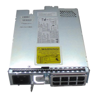
Step 1 Holding the replacement power supply with one hand underneath the module and the other hand holding the handle, turn
the power supply so that its release latch is on the side and align the back end of the power supply (the end with the
electrical connections) to the open power supply slot before carefully sliding the power supply all the way into the slot
until it clicks into place.
Cisco Nexus 9364C-H1 NX-OS Mode Switch Hardware Installation Guide
35
Replacing Components
Replacing a Power Supply Module

 Loading...


