7-8
Cisco PIX Firewall Hardware Installation Guide
78-15170-01
Chapter 7 PIX 535
Installing Failover
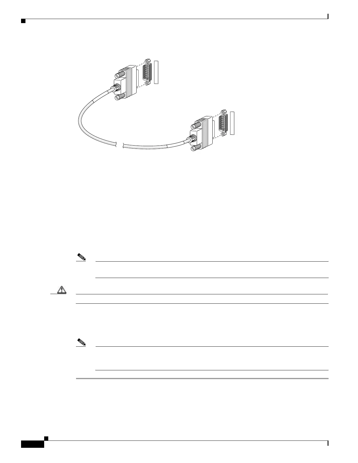
Figure 7-5 PIX 535 Failover Cable Connection
Step 3 Connect the Primary end of the failover cable to the first PIX Firewall unit, that is, the one you have
already configured.
Step 4 Connect the Secondary end of the failover cable to the standby unit.
Step 5 Connect a power cord to the power connector on the rear panel of each unit, and the other end of each
power cord to (preferably separate) power outlets.
Step 6 If you are using Stateful Failover, use one of the following types of connections, that is appropriate for
your system, between the dedicated interfaces on the PIX Firewall units:
• Cat 5 crossover cable directly connecting the primary unit to the secondary unit.
• 100BaseTX full duplex on a dedicated switch or dedicated VLAN of a switch.
• 1000BaseTX full duplex on a dedicated switch or dedicated VLAN of a switch.
Note For Stateful Failover on the PIX 535, you must use a Gigabit Ethernet (GE) failover link with
GE interfaces.
Caution Do not turn the power on until the units are connected and the primary unit is configured completely.
Step 7 Power the primary unit on first, then power on the secondary unit. Within a few seconds, the active unit
automatically downloads its configuration to the standby unit.
If the primary unit fails, the secondary unit automatically becomes active.
Note All enabled interfaces must be connected between the active and standby units. Only configure
the active unit. On the PIX 535, the active unit is indicated by the ACT LED on the front of the
unit.
F
A
I
L
O
V
E
R
F
A
I
L
O
V
E
R
12395
S
E
C
O
N
D
A
R
Y
P
R
I
M
A
R
Y
Primary end
Secondary end

 Loading...