4-13
Cisco PIX Firewall Hardware Installation Guide
78-15170-01
Chapter 4 PIX 515/515E
Removing and Replacing the PIX 515/515E Chassis Cover
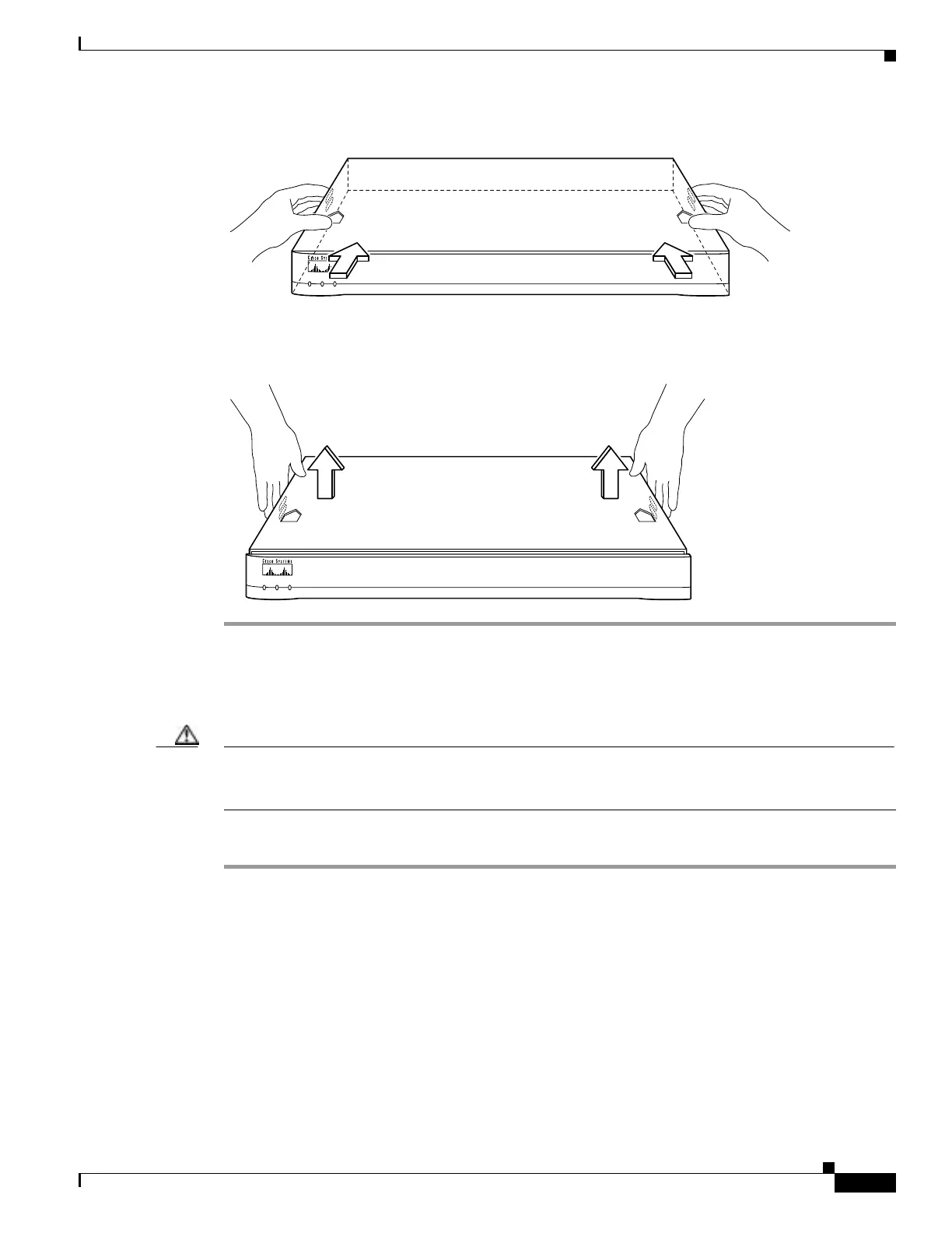
Figure 4-14 Pushing Back the Top Panel
Step 5
Pull the top panel up as shown in Figure 4-15. Put the top panel in a safe place.
Figure 4-15 Pull the Top Panel up to Remove
Replacing the Chassis Cover
Caution Do not operate PIX Firewall units without the top panel installed. The top panel protects the internal
components, prevents electrical shorts, and provides proper air-flow for cooling the electronic
components.
Complete the following to replace the chassis cover:
Step 1 Place the chassis on a secure surface with the front panel facing you.
Step 2 Hold the top panel so the tabs at the rear of the top panel are aligned with the chassis bottom.
Step 3 Lower the front of the top panel onto the chassis, making sure that the top panel side tabs fit under the
chassis side panels.
Step 4 Slide the top panel toward the front, making sure that the top panel tabs fit under the chassis back panel,
and the back panel tabs fit under the top panel.
Step 5 Fasten the top panel with the screws you set aside earlier.
Step 6 Reinstall the chassis on a rack, wall, desktop, or table.
P
O
W
E
R
ACT NETWORK
PIX Firewall
SERIES
24285
24286
P
O
W
E
R
ACT NETWORK
PIX Firewall
SERIES

 Loading...