3-2
Cisco PIX Security Appliance Hardware Installation Guide
78-15170-03
Chapter 3 PIX 506/506E
PIX 506/506E Product Overview
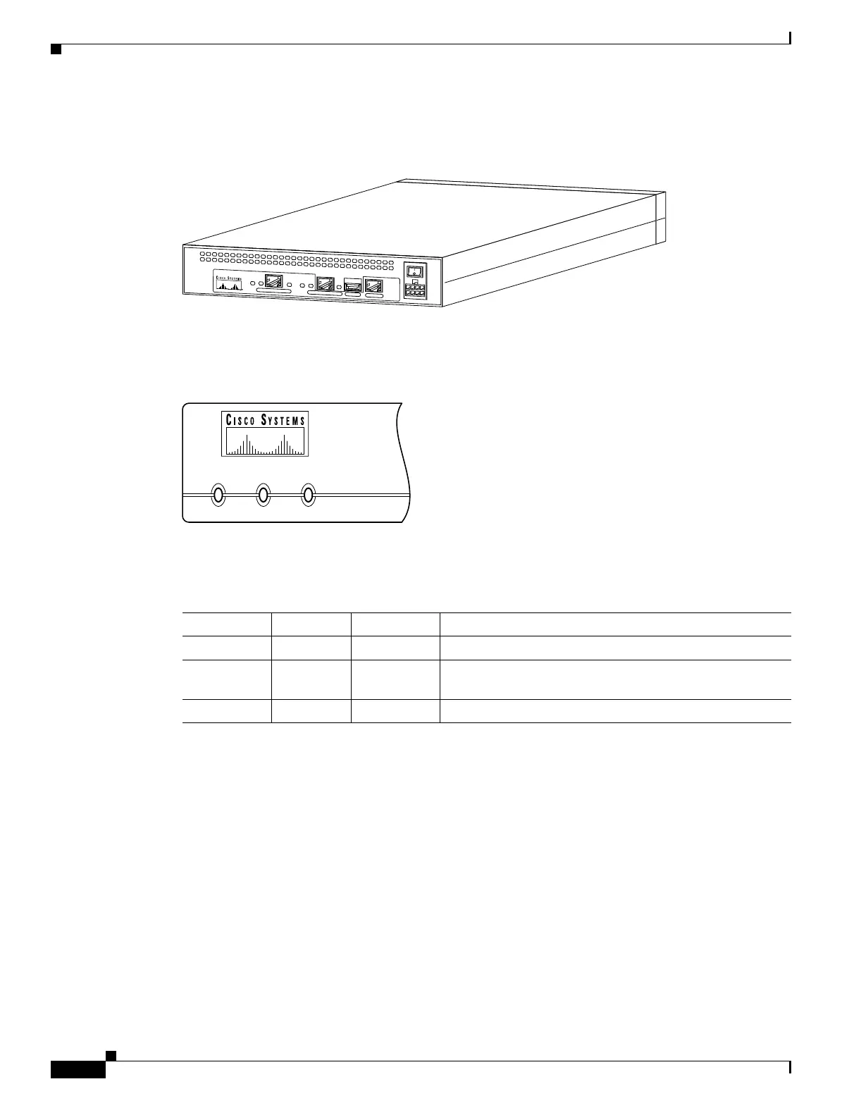
Figure 3-2 shows the rear view of the PIX 506/506E.
Figure 3-2 PIX 506/506E Rear Panel
Figure 3-3 shows the PIX 506/506E front panel LEDs.
Figure 3-3 PIX 506/506E Front Panel LEDs
Table 3-1 lists the states of the PIX 506/506E front panel LEDs.
67947
CONSOLE
ETHERNET 0
A
C
T
L
I
N
K
L
I
N
K
D
C
P
O
W
E
R
IN
P
U
T
A
C
T
USB
ETHERNET 1
POWER ACT NETWORK
25735
Table 3-1 PIX 506/506E Front Panel LEDs
LED Color State Description
POWER Green On The unit has power.
ACT Green Flashing Active indicator—On when the software image has been
loaded on the security appliance.
NETWORK Green Flashing On when at least one network interface is passing traffic.