7-12
Cisco PIX Firewall Hardware Installation Guide
78-15170-01
Chapter 7 PIX 535
Installing a Memory Upgrade
Step 5 Locate the wrist grounding strap in the accessory kit and connect one end to the unit or to the
PIX Firewall chassis, and securely attach the other to your wrist so it contacts your bare skin.
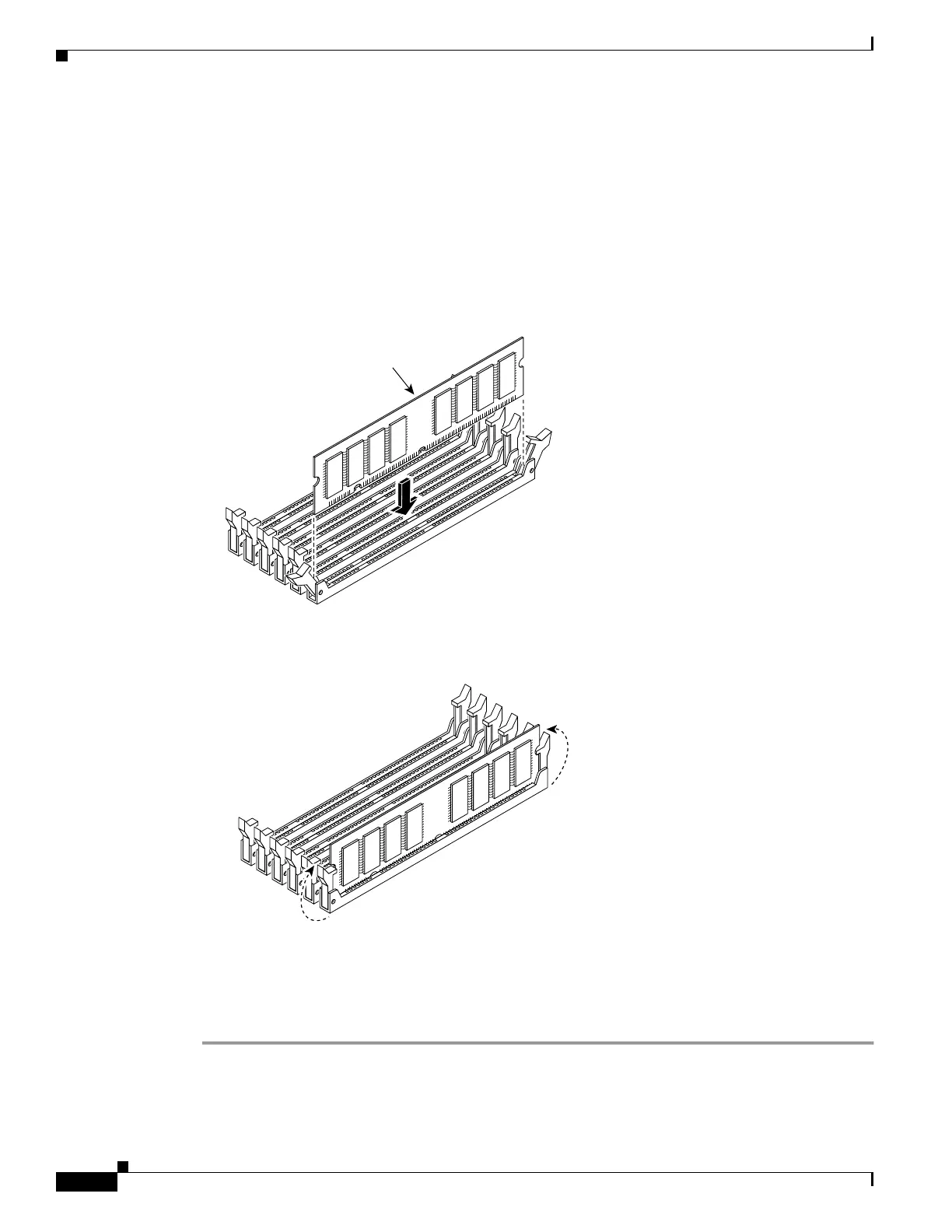
Step 6 With the wrist strap on your wrist, carefully grasp the memory strip from either end. Note that a DIMM
strip has notches.
Step 7 Install the first DIMM in socket J41, and the second DIMM in socket J44 as shown in Figure 7-7 and
Figure 7-8, by opening the two plastic wing connectors, inserting the strip, and closing the wing
connectors.
Figure 7-8 Inserting a DIMM Memory Strip in the PIX 535
Figure 7-9 Securing a DIMM Memory Strip in the PIX 535
When you finish inserting new RAM memory, reinstall the tray on the PIX 535. Reattach the screws. If
desired, rack mount the PIX Firewall and attach all cables and cords as discussed in previous sections.
After the PIX Firewall is installed, you can view the amount of RAM memory in the system startup
messages or with the show version command.
89067
DIMM
J45
J44
J43
J42
J41
J40
J45
J44
J43
J42
J41
J40
89068

 Loading...


