9-10
Cisco SCE8000 10GBE Installation and Configuration Guide
OL-26784-02
Chapter 9 Removal and Replacement Procedures
Installing a DC-Input Power Supply
Step 5 Remove the four screws securing the terminal block cover, and slide the cover off of the terminal block.
(See Figure 9-5.)
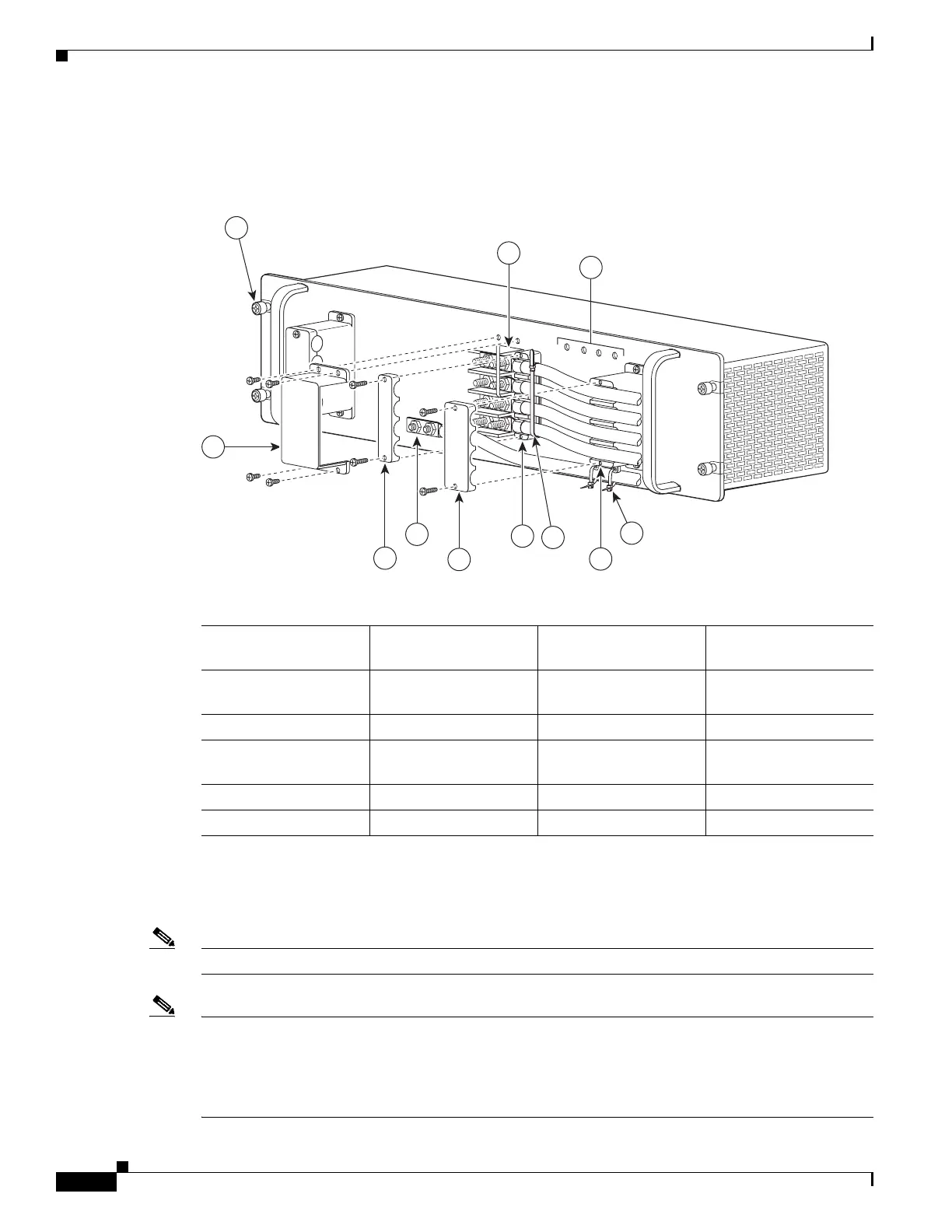
Figure 9-5 DC-Input Front Panel for 2700-W DC-Input Power Supply
Step 6
Attach the appropriate lugs to the DC-input wires and ground wire. The wires should be sized according
to local and national installation requirements. Use only copper wire. The maximum width of a lug is
0.600 inch (15.2 mm).
Note Use fine-stranded copper conductors rated for 90°C (194°F) for North American installations.
Note The power supply terminal block lug opening width is 0.62 inch (15.8 mm). The terminal posts are
centered 0.625 inches (15.88 mm) apart and are 1/4-20 threaded. We recommend that you use an
appropriately sized industry standard 2-hole, standard barrel compression lug. The power supply ground
studs, located below the terminal block, are also threaded 1/4-20 and require two 1/4-inch split-ring
washers and two 1/4-20 hex nuts.
1 Captive installation
screw
7 Cable holder cover
2 DC power cable
terminal block
8 Cable holder
3 Status LEDs 9 Tie-wrap
4 DC power cable
terminal block cover
10 Cable holder
5 Cable holder cover 11 Tie-wrap
6 Ground
132219
PWR-2700-DC/4
-VE-1
-VE-1
-VE-2
-VE-2
IN
P
U
T1
O
K
48V
-60V
=40A
IN
PU
T
2
O
K
48V
-6
0V
=40A
FA
N
O
K
O
U
TP
U
T
FA
I
L
ALL FASTENERS M
UST BE F
ULL
Y ENG
AGED
PRIOR TO OPERA
TING TH
E POW
ER SUPPLY
3
2
6
4
10
1
8
5
7
11
9

 Loading...


