9-11
Cisco SCE8000 10GBE Installation and Configuration Guide
OL-26784-02
Chapter 9 Removal and Replacement Procedures
Installing a DC-Input Power Supply
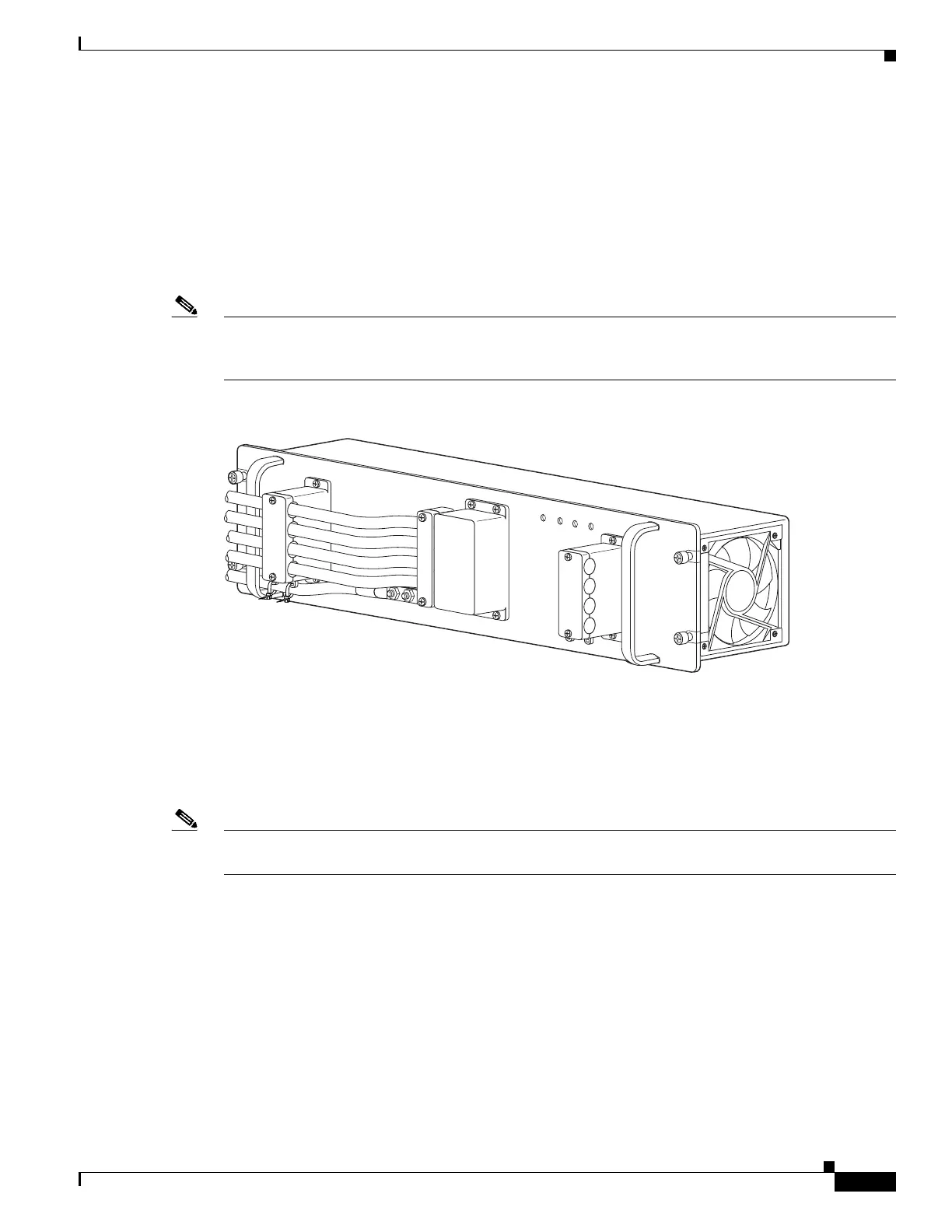
Step 7 Connect the DC-input wires to the 2700 W power supply terminal block . Depending on which side you
are connecting the DC-input wires, be sure that the DC-input wires rest in the appropriate cable holder.
Figure 9-6 shows DC-input wires coming in from the left side.
Connect the DC-input wires to the 2700 W power supply terminal block in this order:
• Ground
• Negative (—)
• Positive (+)
Note When you tighten the terminal nuts, make sure they are snug. Do not over tighten them. The
recommended torque strength is 20 inch-pounds. Over tightening the terminal nuts can break the
terminal block (Maximum torque: 36 inch-pounds).
Figure 9-6 DC-Input Wires on Left Side
When installing the unit, the ground connection must always be made first and disconnected last.
Step 8 Secure the ground cable to the cable holder with the two cable-ties.
Step 9 Retrieve the cable holder covers from the plastic bag and attach them to the front panel at the locations
shown in Figure 9-3.
Note If the cable holder illustrated as number 5 and 8 in Figure 9-3 does not hold the DC input cables snugly,
use a long cable tie to secure the cable holders as illustrated in number 9.
Step 10 Secure the terminal block cover using four screws and the terminal block barriers with two screws each.
132220
IN
PU
T1
O
K
48V
-60V
=40A
IN
P
U
T2
O
K
48V
-60V
=40A
FA
N
O
K
O
U
TP
U
T
F
A
IL
ALL FASTENERS M
UST BE FULLY ENGAGED
PRIOR TO OPERATING THE POW
ER SUPPLY
PWR-2700-DC/4

 Loading...


