10
Note The power supply terminal block lug opening width is 0.62 inch (15.8 mm). The terminal posts are centered
0.625 inches (15.88 mm) apart and are 1/4-20 threaded. We recommend that you use an appropriately sized
industry standard 2-hole, standard barrel compression lug. The power supply ground studs, located below the
terminal block, are also threaded 1/4-20 and require two 1/4-inch split-ring washers and two 1/4-20 hex nuts.
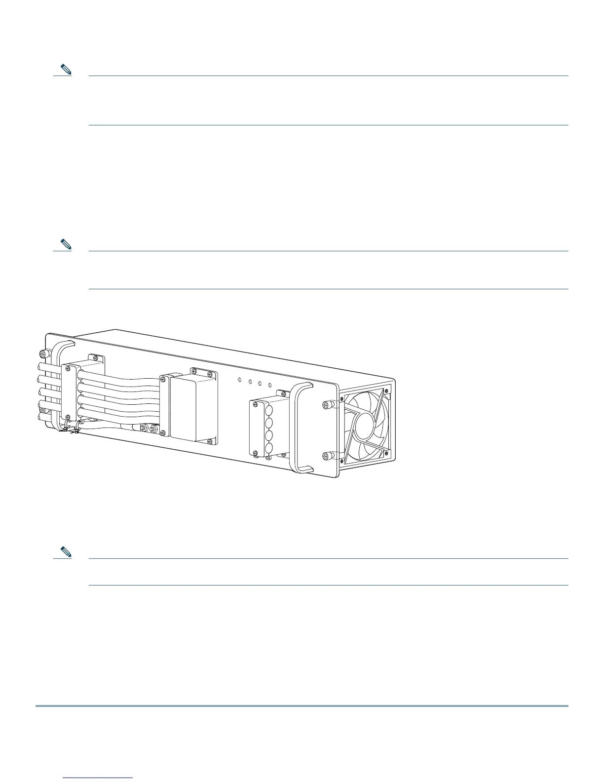
Step 7 Connect the DC-input wires to the 2700 W power supply terminal block. Depending onto which side you are
connecting the DC-input wires, be sure that the DC-input wires rest in the appropriate cable holder. Figure 7 shows
DC-input wires coming in from the left side.
Connect the DC-input wires to the 2700 W power supply terminal block in this order (Figure 7):
• Ground
• Negative (-)
• Positive (+)
Note When you tighten the terminal nuts, make sure they are snug. Do not overtighten them. Recommended torque
strength is 20 inch-pounds. Over-tightening the terminal nuts can break the terminal block (maximum torque:
36 inch-pounds).
Figure 7 DC-Input Wires on Left Side
When you install the unit, the ground connection must always be made first and disconnected last.
Step 8 Secure the ground cable to the cable holder using the two cable-ties.
Step 9 Retrieve the cable holder covers from the plastic bag and attach to the front panel at the locations (see Figure 6).
Note If the cable holder illustrated as number 5 and 8 in Figure 6 does not hold the DC input cables snugly, use a long
cable tie to secure the cable holders as illustrated in number 9.
Step 10 Secure the terminal block cover using four screws and the terminal block barriers with two screws each.
Step 11 Turn on the DC inputs and verify power supply operation by checking the power supply front panel LEDs.
The power supply rear panel LEDs should be in the following states:
• Input OK LED is green
• Fan OK LED is green
• Output Fail LED is not lit
If the LEDs indicate a power problem, see the “Troubleshooting” section on page 21.
132220
IN
P
U
T1
O
K
48V
-60V
=40A
IN
P
U
T2
O
K
48V-60V
=
40A
FA
N
O
K
O
UT
P
UT
FA
IL
ALL FASTENERS MUST BE FULLY EN
GAGED
PRIOR TO OPERATING THE POW
ER SUPPLY
PWR-2700-DC/4