 Loading...


Do you have a question about the Cisco TelePresence MX200 G2 and is the answer not in the manual?
| Resolution | 1920 x 1080 |
|---|---|
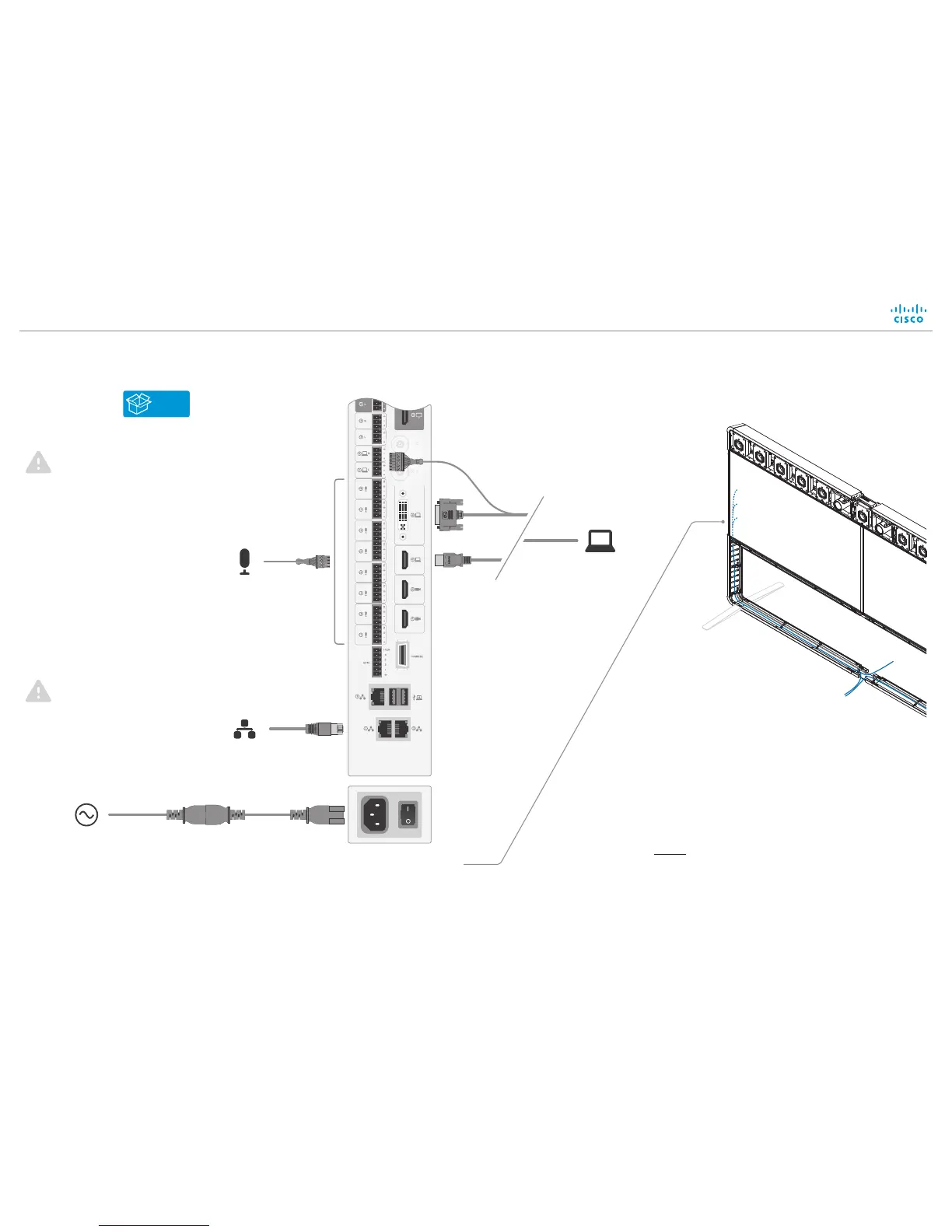
| Network | 10/100/1000 Ethernet |
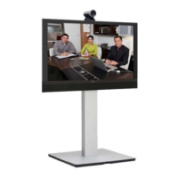
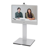
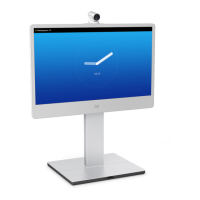
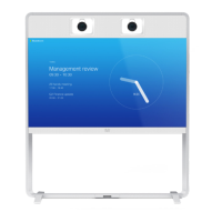
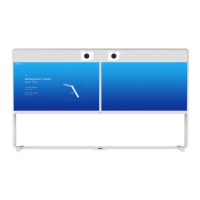
| Product Type | Video conferencing system |
| Display Size | 42 in |
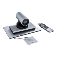
| Camera | PrecisionHD 1080p Camera |
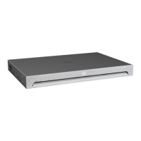
| Codec | Cisco TelePresence Codec |
| Video Inputs | HDMI, DVI-I |
| Video Outputs | HDMI |
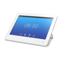
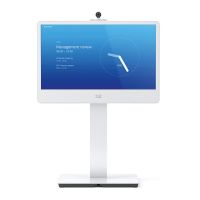
| Control | Cisco Touch 10 |
| Video Standards | H.264 |
| Connectivity | HDMI |
| Codec Support | H.264 |
| Resolution (fps) | 1080p30 |