When installing or removing the power supply module, ensure that the Cisco UBR-RFSW-ADV is powered
off and that you have disconnected all power cables.
Caution
When inserting or removing the power supply from the Cisco UBR-RFSW-ADV chassis, you must use
a screwdriver to tighten and loosen the captive installation screws.
Caution
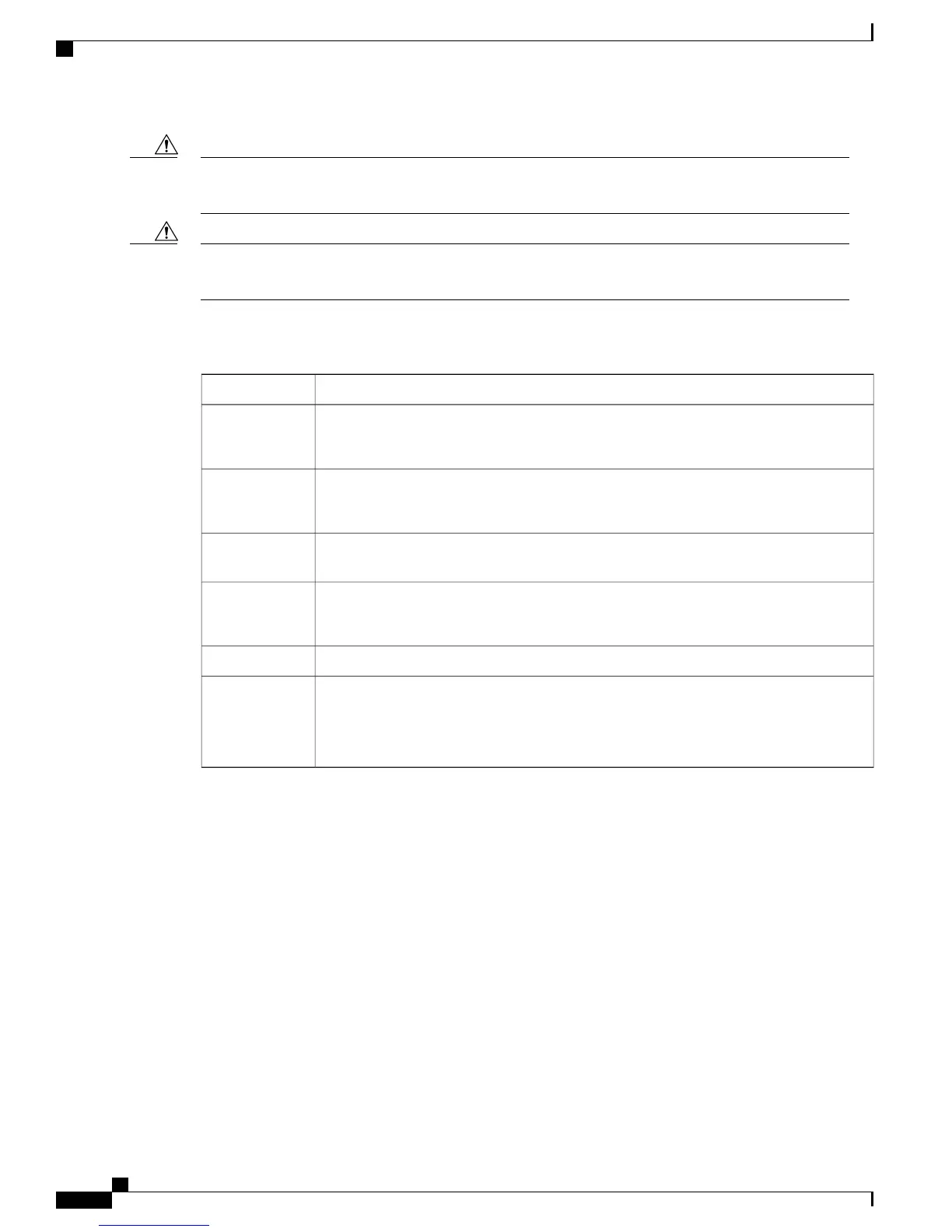
The table below lists the power requirements for the Cisco UBR-RFSW-ADV.
Table 2: Cisco UBR-RFSW-ADV Power Requirements
RequirementParameter
Worldwide ranging DC (-40.5 to -72 V: -48 V nominal)
Nominal 23W; maximum 23 W
Power Input DC
Worldwide ranging AC (100 to 240 VAC, 50 to 60 Hz)
Nominal 47W; maximum 105 W
Power Input AC
Nominal 70W; maximum 128 WPower Input AC
and DC
Maximum (DC): 30 W
Maximum (AC): 30 W
Power
Consumption
IEC320 connectorAC Input Plug
DC input connection uses a terminal block—DMKDS 2.5, 3- position connector.
Recommended conductor cross-section: 14 AWG
Maximum conductor cross-section: 12 AWG
DC Input
Connection
For information about the PIDs for the PSM, see Cisco UBR-RFSW-ADV Components Part Numbers and
Product Identifiers.
Cisco uBR Advanced RF Switch Hardware Installation Guide
12 OL-24104-01
Introduction
Power Supply Module
 Loading...