Power Supply Module
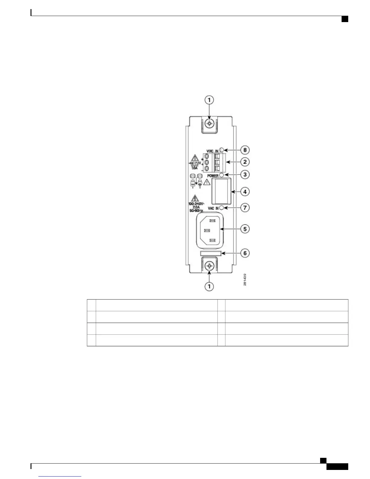
Figure 11: Power Supply Module on the Cisco UBR-RFSW-ADV
AC input plug5Captive screws1
Retainer loop for holding AC power cord6DC input connector2
AC input LED7Power LED3
DC input LED8Power switch (On/Off)4
The power supply module (PSM) allows either an AC, or DC connection, or both. If both AC and DC are
connected, operation is not affected if either power supply fails.
The panel mount power switch (on/off) disables the output of the PSM. The AC and DC converter stages, if
powered, will remain active.
For information on power supply LEDs, see Power Supply LED Behavior
Cisco uBR Advanced RF Switch Hardware Installation Guide
OL-24104-01 11
Introduction
Power Supply Module
 Loading...