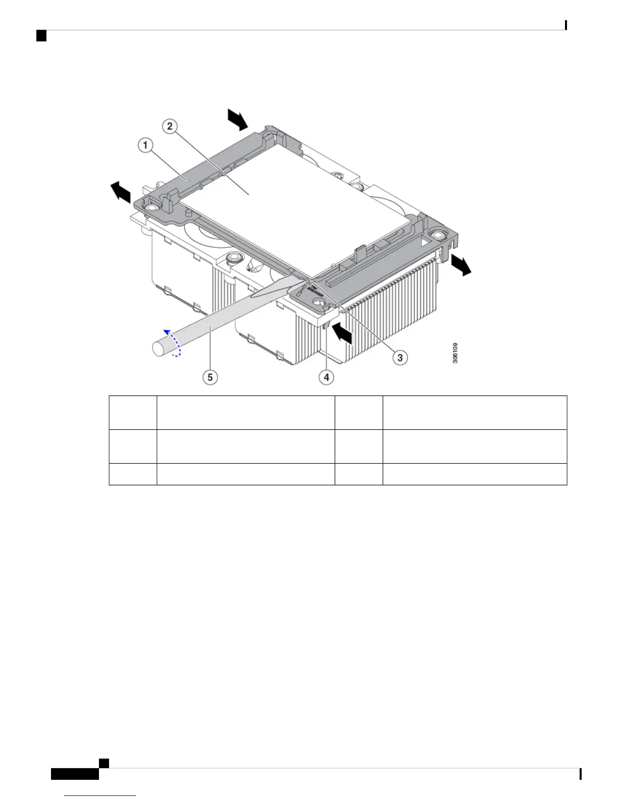
Figure 45: Separating the CPU Assembly From the Heatsink
CPU-carrier inner-latch nearest to the TIM
breaker slot
4CPU carrier1
#1 flat-head screwdriver inserted into TIM
breaker slot
5CPU2
-TIM BREAKER slot in CPU carrier3
b) Pinch inward on the CPU-carrier clip that is nearest the TIM breaker slot and then push up to disengage the clip
from its slot in the heatsink corner.
c) Insert the blade of a #1 flat-head screwdriver into the slot marked TIM BREAKER.
In the following step, do not pry on the CPU surface. Use gentle rotation to lift on the plastic surface of
the CPU carrier at the TIM breaker slot. Use caution to avoid damaging the heatsink surface.
Note
d) Gently rotate the screwdriver to lift up on the CPU until the TIM on the heatsink separates from the CPU.
Do not allow the screwdriver tip to touch or damage the green CPU substrate.
Note
e) Pinch the CPU-carrier clip at the corner opposite the TIM breaker and push up to disengage the clip from its slot
in the heatsink corner.
f) On the remaining two corners of the CPU carrier, gently pry outward on the outer-latches and then lift the
CPU-assembly from the heatsink.
Handle the CPU-assembly by the plastic carrier only. Do not touch the CPU surface. Do not separate the
CPU from the plastic carrier.
Note
Cisco UCS C480 M5 Server Installation and Service Guide
98
Maintaining the Server
Replacing a CPU and Heatsink

 Loading...