CPU module bay 1
The system must have at least one CPU
module in bay 1 to boot.
It must also have either a CPU module or
a blank filler module in bay 2.
13Power supply status LED6
CPU module bay 2
If no CPU module is present in bay 2, there
must be a blank filler module in bay 2 or
the system will not boot.
14Network link activity LED7
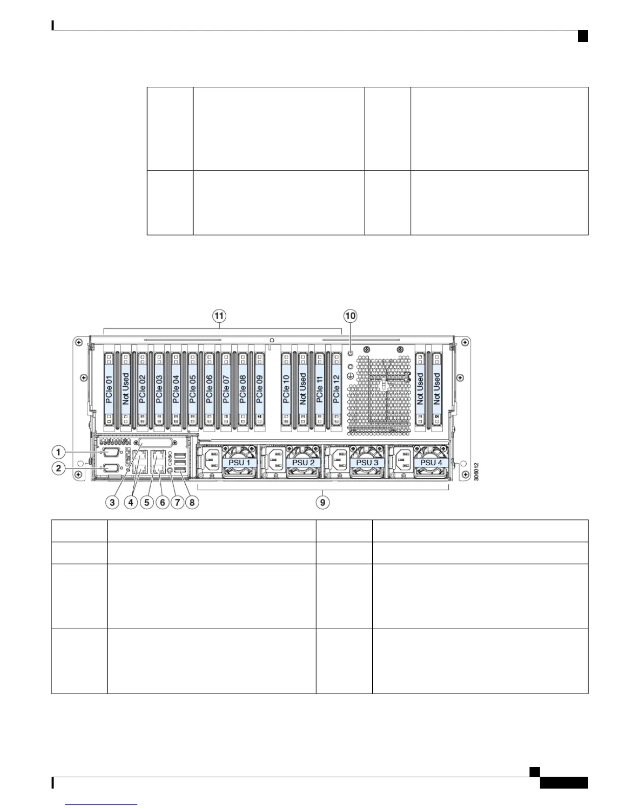
Cisco UCS C480 M5 Server Rear Panel Features
For definitions of LED states, see Rear-Panel LEDs, on page 32.
Figure 2: Cisco UCS C480 M5 Server Rear Panel
Rear identification button/LED7Serial port COM 1 (DB-9 connector)1
USB 3.0 ports (three)8VGA video port (DB-15 connector)2
Power supplies 1 – 4 (hot-swappable, redundant as
2+2 (default) or 3+1)
See Power Specifications, on page 128 for
specifications and supported options.
9Not used at this time3
Threaded holes for dual-hole grounding lug101-Gb/10-Gb Ethernet ports (LAN1 upper, LAN2
lower)
The dual LAN ports can suport 1 Gbps and 10
Gbps, depending on the link-partner capability.
4
Cisco UCS C480 M5 Server Installation and Service Guide
3
Overview
External Features

 Loading...