Yes
(secondary
slot)
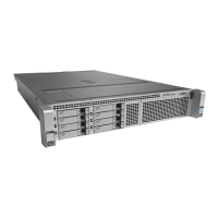
YesYesFull heightFull lengthx24 connectorGen-3 x162
YesNoYesFull heightFull lengthx24 connectorGen-3 x83
YesYesYesFull heightFull lengthx24 connectorGen-3 x164
YesNoYesFull heightFull lengthx24 connectorGen-3 x85
YesYesYesFull heightFull lengthx24 connectorGen-3 x166
YesNoYesFull heightFull lengthx24 connectorGen-3 x87
YesYesYesFull heightFull lengthx24 connectorGen-3 x168
NoNoNoFull heightFull lengthx24 connectorGen-3 x89
NoYesNoFull heightFull lengthx24 connectorGen-3 x1610
NoNoNoFull heightFull lengthx24 connectorGen-3 x811
NoNoNoFull heightFull lengthx8 connectorGen-3 x812
PCIe Population Guidelines and Restrictions
Note the following guidelines and restrictions:
• Control of the PCIe sockets is divided between the CPUs that are present in the system. Some PCIe slots
are not available if your system does not have CPU module 2 installed:
• If your system has four CPUs, all PCIe slots are supported.
• If your system has only two CPUs (CPU module 2 is not present), see the following table for the
PCIe slots that are supported.
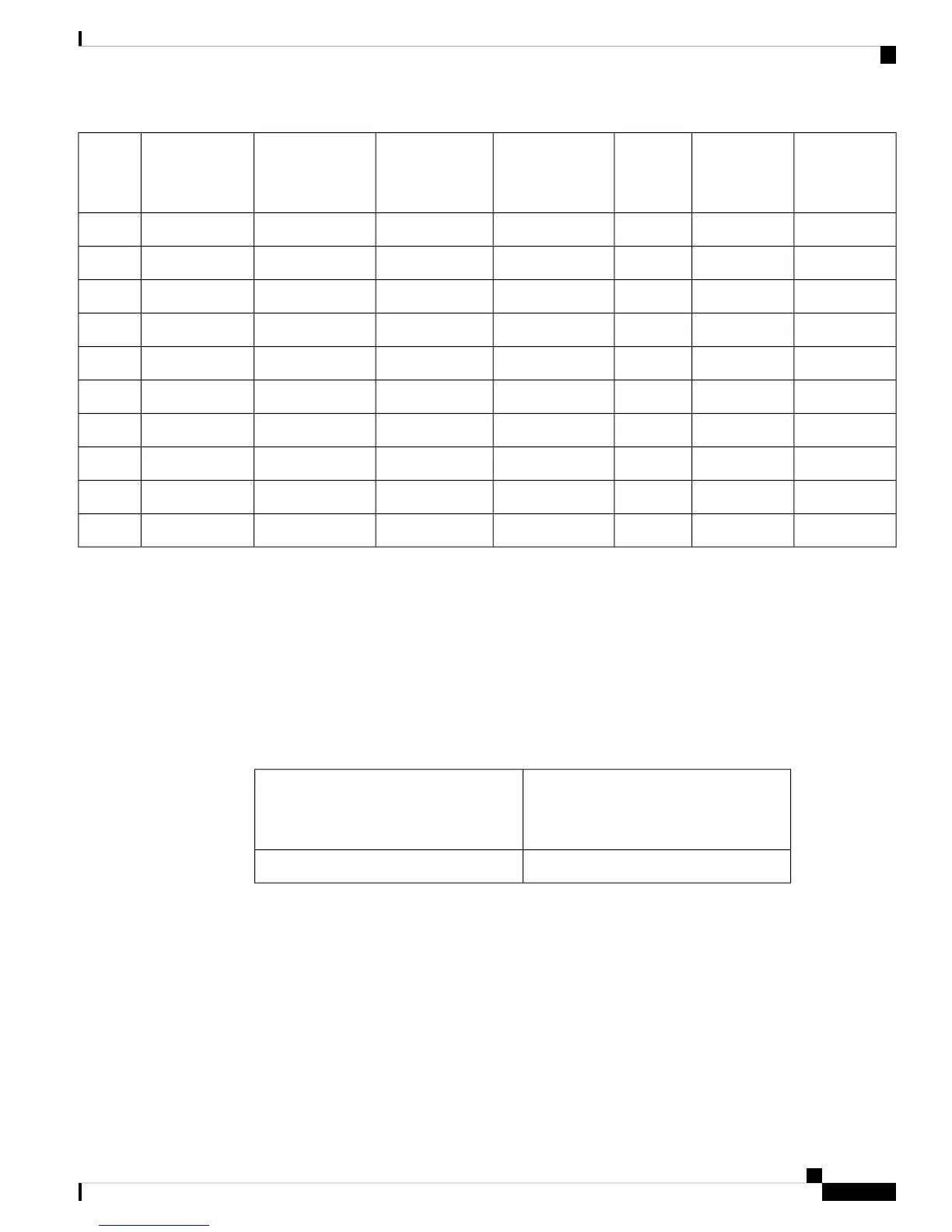
PCIe Slots Controlled by CPU Module
2
(CPUs 3 and 4)
PCIe Slots Controlled by CPU Module
1
(CPUs 1 and 2)
3, 4, 6, 7, 11, 121, 2, 5, 8, 9, 10
• If the rear drive-bay module is installed, PCIe slot 12 is not available because of internal clearance.
• If the server has a rear RAID controller card, it must be installed in PCIe slot 11 or slot 10.
• If the server has a rear NVMe switch card, it must be installed in PCIe slot 10.
Replacing a PCIe Card
Before installing PCIe cards, see PCIe Slot Specifications and Restrictions, on page 89.
Cisco UCS C480 M5 Server Installation and Service Guide
91
Maintaining the Server
Replacing a PCIe Card
 Loading...