EasyManuals Logo

Cisco UCS S3260 Service Note

Cisco UCS S3260
14 pages
To Next Page IconTo Next Page
To Previous Page IconTo Previous Page
Page #10 background imageLoading...
Page #10 background image
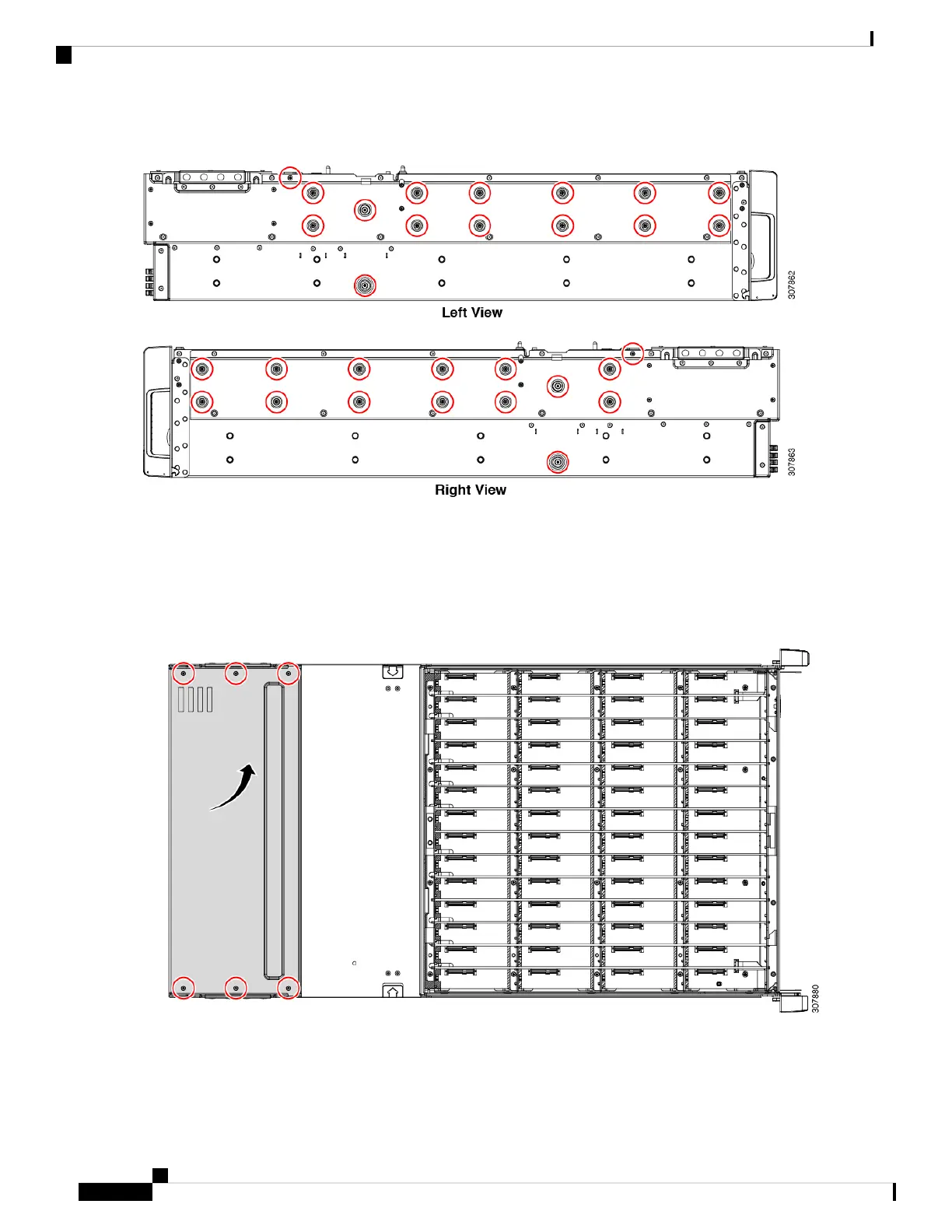
Figure 1: Location of Mounting Screws on Chassis Exterior (Horizontal View)
Step 2 Remove the SSD backplane cables.
a) Using a screwdriver, rotate each of the top rear cover screws counter-clockwise until it disengages.
b) Remove the top rear cover.
The following image shows the location of the rear top cover screws.
Figure 2: Location of Rear Top Cover and Screws
c) Reach down to grasp the SSD backplane cable connectors, then disconnect the cables from the SSD backplane and
Midplane assembly.
d) Cut the cable tie that secures the SSD backplane cables to the chassis.
Cisco UCS S3260 Storage Server PCBA Disassembly For Commission Regulation (EU) 2019/424 Service Note
6
Recycling the PCB Assembly (PCBA)

Other manuals for Cisco UCS S3260

Questions and Answers:

Question and Answer IconNeed help?

Do you have a question about the Cisco UCS S3260 and is the answer not in the manual?

Cisco UCS S3260 Specifications

General IconGeneral
Drive BaysUp to 56
Maximum Storage CapacityUp to 600 TB
Power SupplyUp to 4 hot-plug power supplies
Product TypeStorage Server Chassis
Supported DrivesSAS, SATA
ProcessorsUp to two Intel Xeon Scalable processors
MemoryUp to 1.5 TB DDR4 RAM
Power SuppliesRedundant 80+ Platinum power supplies
Total Drive Bays56
ManagementCisco UCS Manager
CompatibilityCisco UCS system
Form Factor4U rack

Related product manuals