Page 12
6. ASSEMBLY/DISASSEMBLY STARTER
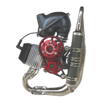
Figure 18
1. Remove 4 screws (Fig.18)
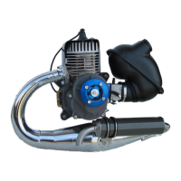
2. Remove the screw (Fig.20) for to arrive
to the pulley
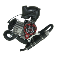
3. Remove the pulley (Fig.21)
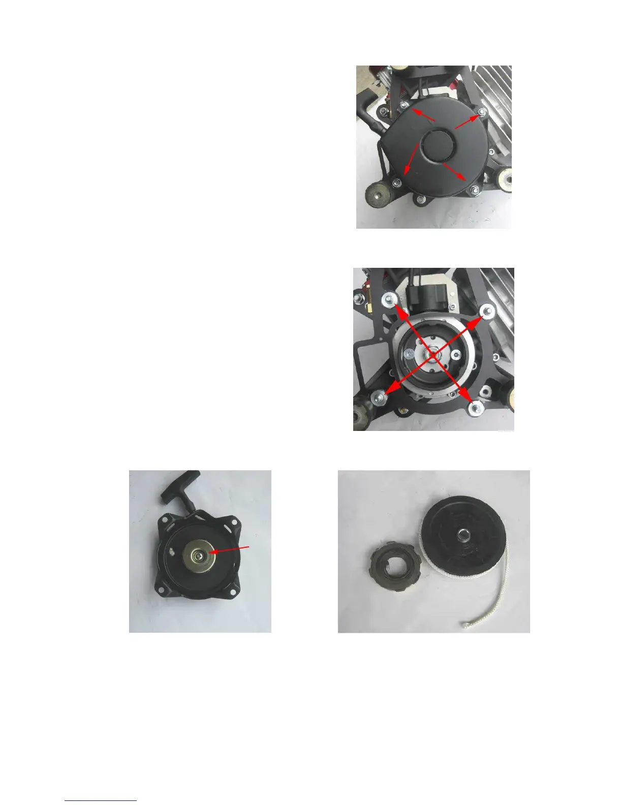
4. Control the screws (Fig.19) are in a good
conditions and locked.
1. Install the pulley and tighten the screw
(pict. 20) to the specified torque
TORQUE : 15Nm( 1,5 kgf/m)
2. Insert the starter in 4 screws (Fig.19)
3. Tighten the screws (Fig.18) to the
specific torque using light locking agent
TORQUE: 12Nm (1.2 kgf/m)
Figure 19
Figure 20
Figure 21