a. Put both media holder disks on the
media holder shaft to make the media
holder assembly
Adjust both disks according to the
width of the roll media so that they
are the same distance from the center
of the media holder shaft and inside
the media core.
b. Insert the media holder assembly into
the media core.
c. Load the media into the printer by
referring to the diagrams and the
following steps.
d. Open the top cover all the way until
it stops.
e. Unlock the printhead assembly by
pushing the printhead release lever
and raise it until it stops and stands
upright. At the same time unlock the
transparent sensor guide by pushing
the transparent sensor guide release
lever and raise it until it stops.
f. Unlock the media guide lock screw
and move both side media guides to
their maximum outward position.
g.. Install the roll of media by placing the
4
Media (Paper) Installation
media holder shaft onto the round notches
on the media guides and media holder shaft
supporting plates.
h. Move both media guides using both hands
so that they come into contact with the
edges of the roll. There should be no space
between media guides and media.
i. Lock the media guides with the media guide
lock screw turned clockwise.
j. Route the roll media over the platen out
to the front of the printer.
k. First lower the transparent sensor guide and
push down gently to lock. Then lower the
printhead assembly fully and push down
firmly on the top edge by the ribbon holders
to lock in place.
l. The roll media is now loaded. Lastly close
the top cover.
Paper path for
outside wound media
Paper path for
inside wound media
The printer’s media and ribbon are aligned
centrally within the printer’s mechanism. The
media (paper) is automatically aligned
centrally by the media guides. To align
the ribbon with the media being used, adjust
the flange as follows:
a. First turn the Lock Nut on the ribbon
bobbin anti-clockwise, then turn the
Ribbon Positioning Nut anti-clockwise to
move the Flange towards the center of the
ribbon bobbin and to align it with the edge
of the media being used.
b. Referring to the scale on the top of the
mechanism, adjust the flange so that the
ribbon is put in the center of the media.
The value of half the ribbon width being
used is the actual value on the scale.
c. Check to see that the ribbon is positioned
properly and fix the ribbon positioning nut
by turning the lock nut clockwise. Repeat
the procedure for the second bobbin.
d. With the two bobbins adjusted, insert one
of them into the supply (unused) ribbon
core and the other in to the take-up (used)
cardboard tube.
e. Unstick the end of the ribbon and use the
adhesive end of the ribbon to stick it to
the takeup core. Then slowly wind some
ribbon on to the take-up core until the
ribbon is secure.
5
Ribbon Installation
f. Unlock the printhead assembly by
pushing down the printhead release lever
and raise it until it stops and stands
upright.
g. Hold both bobbins with a length of
about 300 mm (1 ft) of unwound ribbon
between the bobbins. The left hand grips
the ribbon supply bobbin and the right
hand grips the takeup bobbin.
h. Carefully wrap the unwould ribbon
around the printhead trying to avoid any
wrinkles.
i. Then insert the bobbins in to the drive
gears on the ribbon drive mechanism.
j. Remove any slack and wrinkles by
turning the knob of the ribbon takeup
bobbin clockwise. Do not be afraid to
‘waste’ a little extra ribbon hear to
ensure the ribbon is seated correctly
and wrinkle-free.
k. Lower the printhead assembly with
ribbon and push down firmly to lock. The
ribbon is now loaded. Lastly close the
top cover.
Remember to use Citizen’s thermal transfer
ribbons for the best print quality, reliability
and to maintain your printer’s warranty.
Hold this with
the left hand
Hold this with
the right hand
Ribbon drive gears
Your printer can produce a number of test reports
and configuration prints. This is to show you that
it is operating correctly and that the internal
settings are set correctly.
This section will also introduce you to the
printer’s control panel. The control panel has
many options and is extremely sophisticated giving
the power and ability needed on a high-performance
printer like yours.
However, in many cases, you will only need the
more basic features explained here. Full details of
the complete menu system are shown in the user
manual.
To create a self-test or configuration print, first
load the paper media and ribbon in to the printer
as explained in sections 4 and 5.
a. The switch on the printer. The LCD will display
a number of messages whilst the printer is
starting.
b. If everything is working
correctly, the printer will
display “READY”. If an error
6
Creating a Test and Configuration Print
message is displayed, you should consult your
dealer for further information and advise on what
to do.
c. Press the
key to
display the first menu. It will say
Page Setup. Menu’s with an
asterisk (*) before each item are
referred to as “group menus”.
They are the top level menus.
d. Press the
key to show
the next Group Menu. After
pressing the key a number of
times, you will see the display
saying ‘Test Mode’.
e. Press the key to enter
the test mode menu and to
display the first option available.
The display should show ‘Print
Pattern’.
f. Press the key again to
display the possible test patterns
available. The first one will say
‘Current Settings’.
* Page
Setup
* Test
Mode
Print
Pattern
Current
Settings
Pattern
Sample
Printing
READY
Machine
Info
Thicker media or card
Not for wider or narrower media
If the media you are using is thicker (like a card or
tag, for example) you will need to adjust the
Printhead Adjustment Lever to a higher value to
get a good print quality.
For normal paper and labels , the printer is adjusted
at the factory to the “0” position.
For medium thickness card, move the adjuster to
the “5” position. For very thick (stiff) card, move
the adjuster to the “10” position.
To change the adjuster:
a. Unscrew the small black adjuster release screw.
b. Slide the printhead adjustment lever to the
required position.
c. Re-tighten the black adjuster screw.
d. Ensure the black adjuster screw is tightened
firmly to avoid it moving in operation.
7
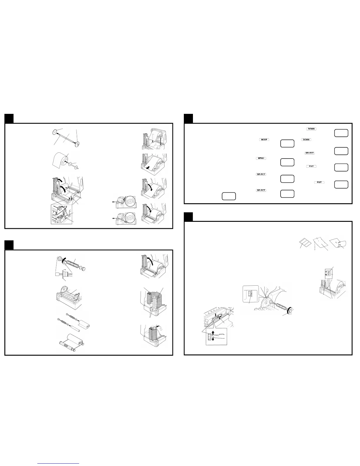
Adjusting the Printer for Specialist Media
Specialist Ribbons
Also including narrow-width ribbons
If you are using a specialist ribbon or one that is
less than the full width of the printer, it may be
neccessary to adjust the ribbon tension to avoid
ribbon wrinkle and “Ribbon Out” errors.
a. Insert a coin in to the slot on the ribbon drive
cover as shown below. This stops the white
plastic gear from rotating.
b. With a ribbon bobbin inserted in to the rear
holder, turn the bobbin clockwise or anti-
clockwise to get the correct setting on the
ribbon drive indicator.
The indicator is the left edge of the white plastic
gear visible through the slot in the cover.
c. For narrow media, or if you are getting false
“Ribbon Out” errors on the control panel,
adjust the settings towards ‘0’.
It may be necessary to adjust the “Ribbon Torque”
of the destination ribbon. This is done with a
control panel setting, explained in the full user
manual.
Media Sensor Adjustment
For unusual shaped media, tags, etc.
a. Unlock the printhead assembly and sensor guide
as described in section 4e
b. For black mark
sensing, move
the lower media
sensor so that
the ‘R’ mark is in
the middle of the
black mark on
the media.
c. For punched hole
or notched tag,
move the lower
media sensor so
that the ‘T’ mark
is aligned with
the hole or notch in the media.
d. Read and note the value on the scale on the
media guide plate pointing the ‘T’ mark (not
the ‘R’ mark, even if you are using black mark
sensing)
e. Lower the transparent sensor guide arm fully and
push it down gently to lock.
f. Move the ‘T’ pointer of the upper sensor to the
same scale position as the lower sensor position
noted previously.
g. The media sensor adjustments are now
completed. Lastly lower and close the printhead
assembly and top cover.
g. Press to change from
‘Current Settings’ to ‘Pattern
Sample’. If you miss the option,
just keep pressing the
key and you get back
to it once more.
h. When you have selected the
‘Pattern sample’, press
the
key. The printer
will say ‘Printing’ and the test
pattern should be produced.
i. Once this is done, you can
press to return to the
previous menu. You can now
make other test prints if you
require, such as ‘Machine Info’
or ‘Current Settings’.
j. If you press several
times, you will return to the
Ready screen.
The full control panel menu system has many
options. Full details on how to modify and change
them are given in the user manual.
READY
Media holder disks
Centre
Media holder disks
Roll of media
Media holder
assembly
Transparent
sensor guide
release
Print head release
Media guide
lock screw
Media guides
Ribbon bobbin
Lock Nut
Ribbon Positioning Nut
Scale on mechanism
Ribbon bobbin. Rotate anti-
clockwise for lower setting
White indicator
Coin
Black adjuster
release screw
Printhead
adjustment lever
Standard Labels
Gap between labels
Tags or Card
notches and/or holes
Continuous media
Black mark on reverse
‘T’ mark for labels,
notches and holes
‘R’ mark for black
registration marks
Lower media sensor
Upper
media
sensor

 Loading...


