13
Use with power supply voltage and output in the
specied range.
Applying a voltage that is outside of the specied
range may cause malfunction, damage to the
sensor, electrical shock, and/or re.
Do not use any load that exceeds the rated output.
Using such a load may result in damage to the
output part or re.
Check the wire color and terminal No. when
connecting wires.
An overcurrent protection circuit for the output
transistor and a protection circuit for erroneous
wiring, which uses diodes to prevent reverse
connection, are implemented, but these do not
protect against all incorrect wiring. Incorrect wiring
can result in malfunction, failure, or damage to the
sensor.
Check the instruction manual for wiring colors and
terminal numbers in order to ensure correct wiring.
Check wiring insulation.
Check that wires do not come into contact with
other circuits, that no ground faults occur, and that
the insulator between terminals is not defective.
Otherwise, overcurrent may ow into the sensor,
causing damage.
Keep the cable far away from power cords or other
things that may cause noise. Noise can cause
malfunctions.
Keep unused wires from coming into contact with
other wires.
Do not short-circuit the output transistor.
When a load is short-circuited, overcurrent
protection circuit is triggered to prevent damage to
the output transistor; however, if this state persists,
the output transistor could be damaged.
Overcurrent protection .....approx. 50 mA
Do not use a load that can produce surge voltage.
While an element that protects against surge is
inserted, repeated exposure to surges can lead to
damage. Use relays and solenoid valves that are
equipped with surge absorption elements. If there
is a surge source on the same power supply line,
similarly implement surge protection.
Make sure that the lead wire is free of repeated
bends and tension. This may lead to disconnection.
Pipes can be installed vertically, horizontally, or in
any other orientation. Note that pipes should be
installed so that the uid constantly lls the piping
while it ows through the pipes.
When installing a pipe vertically, making the uid ow
upward can reduce the inuence of air bubbles inside.
If a pipe is narrowed just before the ow rate
sensor, or if there is a valve or other restricting
component on the primary side, cavitation occurs
inside the pipe, preventing accurate measurement.
For this reason, such piping should be installed on
the secondary side of the sensor.
Cavitation...(Vapor cavities that form due to the static
pressure at end points, such as a ship propeller,
dropping below the vapor pressure of the water.
Reduced efciency or screw damage may result.)
However, operating the pump with the secondary
side valve closed may cause the ow rate sensor
to detect pressure waves from the pump, resulting
in incorrect indication. If this occurs, install the
valve on the primary side. When doing so, ensure
that a straight pipe with a diameter of 10 times or
more bore size is installed between the valve and
the ow rate sensor.
Mounting, installation and adjustment
DANGER
WARNING
CAUTION
CAUTION
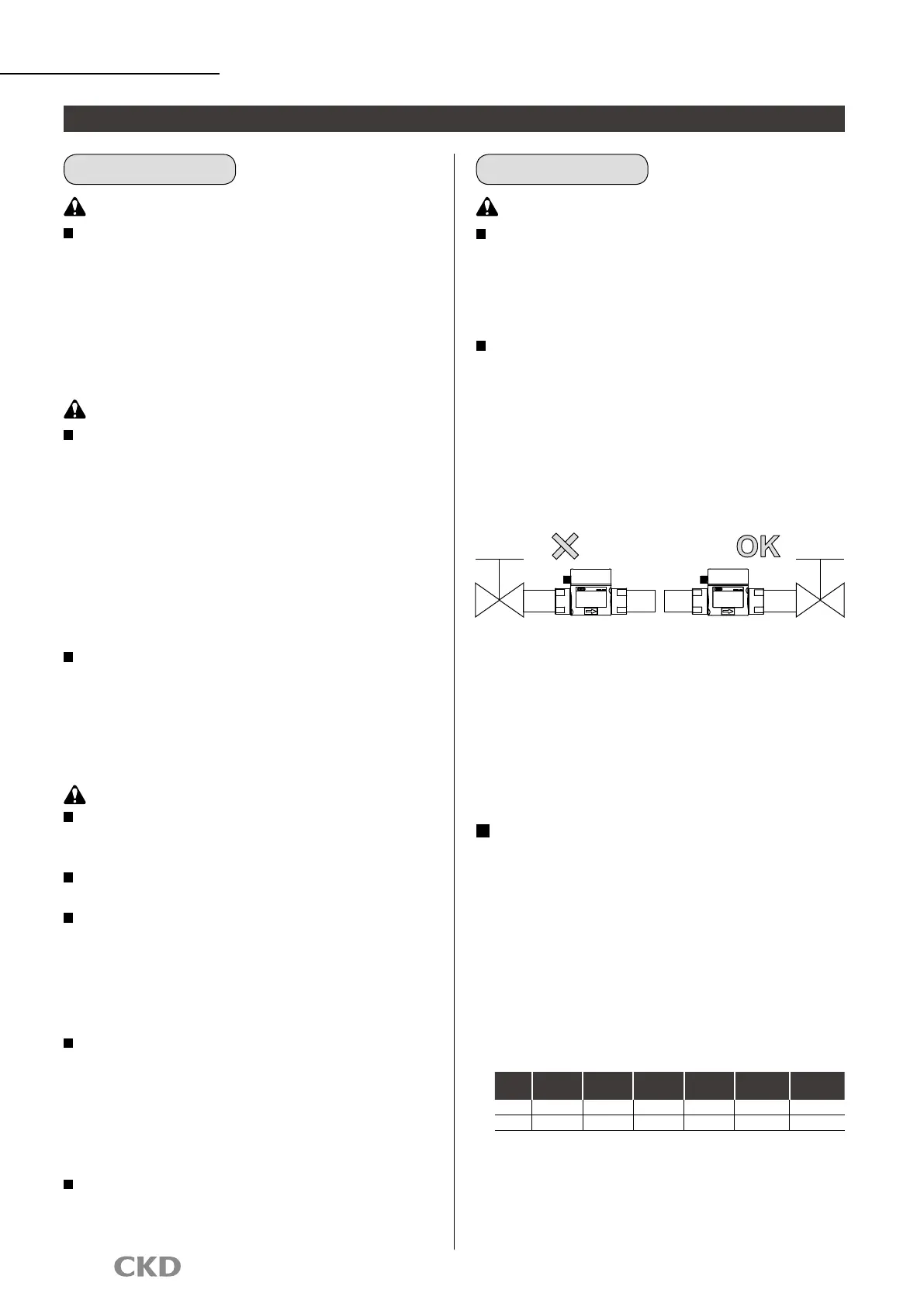
1. Wiring 2. Piping
Using an elbow or bush in the piping
When using an elbow or bush in the piping, provide straight
piping sections of at least 10 D on the IN side and 5 D on
the OUT side when using a WFK2-100 or WFK2-250 Series
model. Note that bore size change by bush should be
limited to one size. Without a straight pipe, measurement
accuracy can be compromised due to disturbances in the
ow rate and/or pressure distribution.
(Straight pipes are not necessary for the WFK2-005,
WFK2-020, and WFK2-050 Series. However, it is
recommended that a straight pipe is installed to ensure
stable measurements.)
* "D" here indicates the inner diameter of the piping material.
Refer to the table below for specic values.
Bore size
Rc3/8
(10A)
Rc1/2
(15A)
Rc3/4
(20A)
Rc1
(25A)
Rc1 1/4
(32A)
Rc1 1/2
(40A)
5D 50 mm 75 mm 100 mm 125 mm 160 mm 200 mm
10D 100 mm 150 mm 200 mm 250 mm 320 mm 400 mm
WFK2
Series
Metering valve
Metering valve
 Loading...