WS1.5", 2" and 2"QC Drawings and Service Manual Page 3
Table of Contents
• WS1.5 Generation 2 shown
Pages
Installation Summary 4
General Specifi cations and Pre-Installation Checklist 5
Valve Port Orientation Diagrams 6-8
Installation Instructions 9-10
System Startup 11
Troubleshooting Procedures 17-20
WS1.5 Control Valve Cycle Positions 21-23
WS2 Control Valve Cycle Positions 23-25
Base Assemblies 30
Injector Graphs 35-39
Motorized Alternating Valve Applications 43-47
No Hard Water Bypass 48-49
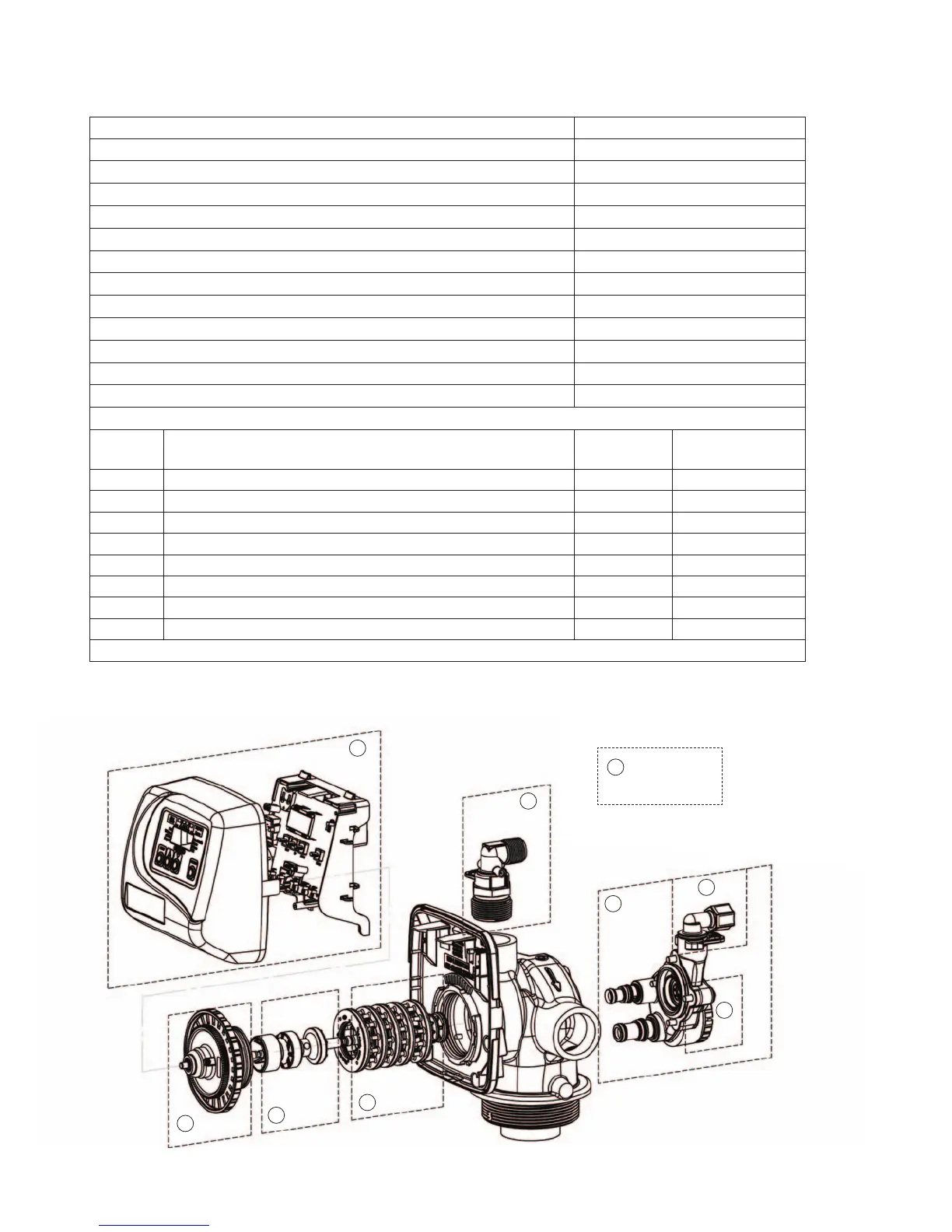
Service Instructions
Service
Step
Description
Exploded
Views
Instructions
1 Front Cover and Drive Assembly * 12
2 Drive Cap Assembly 26-29 13
3 Pistons 26-29 14
4 Spacer Stack Assembly 26-29 14
5,7 Injector Cap, Screen, Injector Plug and Injector 31-33 15
6Refi ll Flow Control Assembly or Refi ll Port Plug 34 15
8 Drain Line Flow Control (DLFC) 40-41 16
9 Water Meter (not shown below) 42 42
* See software-specifi c Programming and Front Cover Manual
1
3
4
7
6
5
8
2
9
Not Shown
• Meter
 Loading...