-
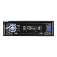
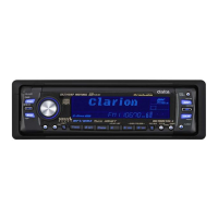
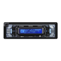
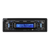
DXZ735MP
TROUBLESHOOTING
Problem Cause
Measure
The mic ropro ce s sor has
malfunctioned due to noise, etc.
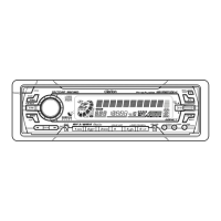
Turn off the p ower, th en press the
[OPEN]
DCP.
Presstheresetbuttonwithathin
rod.
Nothing happens when buttons
are pre sse d.
Display is not accurate.
button an d remove the
Reset button
EXPLANATION OF IC:
1.Terminal Description
052-3382-00 M30624MGA-157GP Main Sysytem Controller
Time base signal input. pin 56
The chip enable signal output to the PLL I- pin 58
The cut off c ontrol signal input from the fil-
C. ter.
pin 5
Remote c ontroller signal input terminal. pin 59
The cut off c ontrol signal input from the fil-
pin 6
The data length selection(8bit/16bit). ter.
pin 7
Positive supply voltage.
pin 8
Jog key signal input. pin 61
Jog key signal input. pin 62
Negative supply voltage.
pin 10
Reset signal input. pin 63
Crystal connection. pin 64
Negative supply voltage. pin 65
At receiving the FM station, this port detec-
pin 13
Crystal connection. ts the stereo signal. At seeking or scanning,
pin 14
Positive supply voltage. this port detects the station detection s ignal.
pin 15
RDS noise discharge signal output.
pin 16
ACC detection signal input. pin 67
Station detection speed up command outp-
pin 17
Backup detection signal input. ut for RDS.
pin 18
Key interrupting signal input. pin 68
Connect to pin 27. pin 69
RDS mute signal output.
pin 20
The power supply control signal output for pin 70
RDS serial data input.
the illumination. pin 71
The power supply control signal output for pin 72
Not in use.
the LCD driver. pin 73
RDS clock pulse input.
pin 22
Clock pulse output to the volume IC.
pin 23
The serial data o utput to the volume IC.
pin 24
PWM s ignal output to control the green. pin 76
CATS LED drive output. pin 77
PWM s ignal output to control the red. pin 78
Muting signal output to the Audio Power A-
pin 27
IE Bus serial data input. mplifier.
pin 28
IE Bus serial data output. pin 79
Muting signal output to suppress the noise
pin 29
Not in use. without Navigation sound interrupting.
pin 30
System muting signal output.
pin 31
The telephone interrupt signal input.
pin 32
Illumination ON s ignal input.
pin 33
The serial data output to the LCD driver. pin 83
The serial data input from the LCD driver. pin 84
The control signal output to internal audio
pin 35
The clock pulse output to the LCD driver. power amplifier.
pin 36
Chip select signal output to LCD. pin 85
Motor antenna control signal output.
pin 37
Power supply ON signal output. pin 86
ON signal output to the 5V power supply.
pin 38
The noise level for RDS.
pin 39
The input terminal of internal A/D convert-
pin 40
MP3 request signal input. er to monitor the radio field strength.
pin 41
MP3 chip selection signal output. pin 89
Input terminal of A/D converter for Key jud-
pin 42
MP3 wakeup signal output. gment.
pin 43
MP3 reset signal output. pin 90
Dual zone muting control signal output.
pin 44
CD main mode status output.
pin 45
Serial data input from the PLL IC. pin 92
Key illumination ON signal output.
pin 46
Serial data output to the PLL IC. pin 93
ACC detec t signal output.
pin 47
The clock pulse output to the PLL IC. pin 94
The chip enable signal output to PLL IC. pin 95
The reference voltage input.
pin 50
Positive supply voltage for the internal an-
pin 51
The destination setting s ignal input. alog section.
pin 52
The destination setting s ignal input. pin 98
MP3 serial data input.
pin 53
The destination setting s ignal input. pin 99
MP3 serial data output.
pin 54
 Loading...