Do you have a question about the Clarion PN-3000P-A and is the answer not in the manual?
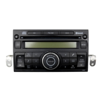
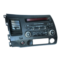
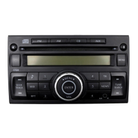
Identifies the NISSAN Automobile Genuine 6CD models.
Details radio, intermediate frequency, and CD section parameters.
Provides critical information and precautions for technicians.
Essential safety instructions for repair and inspection personnel.
Lists main components for reference.
Describes voltage regulators and switching ICs.
Details system controller and EEPROM ICs.
Visualizes the unit's main functional blocks and signal paths.
Pinout diagrams for external connectors.
Flowcharts for diagnosing power and audio problems.
Flowcharts for diagnosing radio and CD functionality.
Visual breakdown of the unit's components.
Comprehensive lists of parts and their numbers.
Detailed list of components for the Switch PWB (B1).
Specific part numbers for resistors and capacitors.
Component placement on Switch PWB (B1) component and solder sides.
Detailed schematic for the Main PWB (B2).
Schematic for the Switch PWB.
Pinout for the TC94A73MFG-201 CD IC.
Pinout for the TMP91CY22IFG mechanism controller.
Instructions for removing key assemblies like CD-PWB and holder.
Steps for removing and installing C-Drive, LO-Motor, M-MTR, UD-Motor.
Explains disc holder, drive unit, loading roller, and shutter operations.
Details motor functions and photo sensor operations.
Visual breakdown of the main unit's components.
List of parts for the main section.
Diagram of the N-Drive-CH unit's components.
List of components for the N-Drive-CH unit.
Exploded view of the upper unit.
List of parts for the upper unit assembly.
Illustrates signal paths and interconnections of the GI-X mechanism.
Highlights major ICs and their relationships.
Detailed list of electrical components for the CD PWB.
Parts list for Sensor-L-FPC and Sensor-U-FPC.
Schematic of the CD PWB (BM1) circuit.
Circuit diagrams for Sensor-L-FPC and Sensor-U-FPC.
| Brand | Clarion |
|---|---|
| Model | PN-3000P-A |
| Category | Car Receiver |
| Language | English |