EasyManua.ls Logo

Clarion PH-2761C-F User Manual

Clarion PH-2761C-F
14 pages
To Next Page IconTo Next Page
Page #1 background imageLoading...
Page #1 background image
PH-2761C
- 1 -
Service Manual
Published by Service Dept.
Printed in Japan
Clarion Co., Ltd.
50 Kamitoda, Toda-shi, Saitama 335-8511 Japan
Service Dept.: 5-66 Azuma , Kitamoto-shi, Saitama 364-0007 Japan
Tel: +81-48-541-2335 / 2432 FAX: +81-48-541-2703
298-6423-00
Jan.2007
ORIGINAL SERVICE MANUAL
This additional service manual is designed to be used to-
gether with the original manual.
Original model Manual No.
PH-2761C-F PH-2761C-A 298-6303-00
PH-2761C-G PH-2761C-B
PH-2761C-H PH-2761C-C
PH-2761C-I PH-2761C-D
PH-2761C-J PH-2761C-E
PH-2761C-K PH-2761C-D
DIFFERENT POINT
CD mechanism and some parts were changed from the
original model(PH-2761C-A/B/C/D/E).
PH-2761C-A/B/C/D/E PH-2761C-F/G/H/I/J/K
CD mechanism 929-0292-80 929-5000-80
Model
Model
Model
Model
Model
HONDA Automobile Genuine
AM/FM Radio CD Stereo
(Pre-AMP Type)
PH-2761C-G
PH-2761C-F
PH-2761C-H
( Genuine No. 39100-SVA-A11 )
( ID No. 4PC0 / ID Label: HM-H )
( Genuine No. 39100-SVA-A11 )
( ID No. 4PC0 / ID Label: HM-B )
( Genuine No. 39100-SVA-C11 )
( ID No. 4PC1 / ID Label: HN-B )
PH-2761C-I
( Genuine No. 39100-SVB-A11 )
( ID No. 4TC0 / ID Label: HP )
PH-2761C-J
( Genuine No. 39100-SVB-C11)
( ID No. 4TC1 / ID Label: HQ )
Model PH-2761C-K
( Genuine No. 39100-SNA-K51 )
( ID No. 4TC6 / ID Label: TL-B )
PH-2761C-F
Question and Answer IconNeed help?

Do you have a question about the Clarion PH-2761C-F and is the answer not in the manual?

Clarion PH-2761C-F Specifications

General IconGeneral
BrandClarion
ModelPH-2761C-F
CategoryCar Receiver
LanguageEnglish

Summary

HONDA Automobile Genuine AM/FM Radio CD Stereo (Pre-AMP Type)

DIFFERENT POINT

Details on changes from original models, including CD mechanism and part number differences.

General Cautions for Repair and Inspection

Safety Precautions During Repair

Essential safety guidelines for engineers, covering part usage, wiring, and general handling during repairs.

Optical Pickup Handling and Care

Specific instructions for safe handling and maintenance of the optical pickup to prevent damage.

ADJUSTMENT

Clock Accuracy Adjustment

Procedure for adjusting the clock accuracy using a frequency counter and specific settings.

IC Pinout and Description

System Controller (UPD703272YGC324-8EAA)

Detailed pin descriptions and terminal functions for the System Controller IC.

Exploded View / Parts List

Escutcheon and Main Sections Parts

Parts list and exploded views for the escutcheon and main sections of the unit.

CD Mechanism Exploded View

Diagrammatic exploded view of the CD mechanism assembly, showing component placement.

CD Mechanism Parts List

Comprehensive list of individual parts for the CD mechanism assembly.

Electrical Parts List

Main PWB Section (B1) Parts

List of electrical components for the Main Printed Wiring Board (PWB) section B1.

Switch PWB Section (B2) Parts

List of electrical components for the Switch Printed Wiring Board (PWB) section B2.

Circuit Diagrams

Main PWB Section (B1) Diagrams

Circuit diagram for the Main Printed Wiring Board (PWB) section B1, illustrating connections and components.

Printed Wiring Board Layouts

Main PWB Section (B1) Layout (Part 1)

Component layout for the Main Printed Wiring Board (PWB) section B1.

Main PWB Section (B1) Layout (Part 2)

Continuation of the component layout for the Main Printed Wiring Board (PWB) section B1.

Switch PWB Sections Layout

Component layouts for Switch PWB-A (B2) and Switch PWB-B (B2) sections.

Block Diagrams

CD Mechanism Block Diagram

Functional block diagram illustrating the CD mechanism's main components and signal flow.
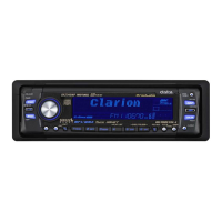
Related product manuals