EasyManua.ls Logo

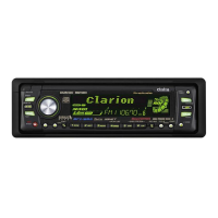
Clarion PU-9079A User Manual

Clarion PU-9079A
23 pages
To Next Page IconTo Next Page
Page #1 background imageLoading...
Page #1 background image
Question and Answer IconNeed help?

Do you have a question about the Clarion PU-9079A and is the answer not in the manual?

Clarion PU-9079A Specifications

General IconGeneral
BrandClarion
ModelPU-9079A
CategoryCar Receiver
LanguageEnglish

Summary

SPECIFICATIONS

General, FM, AM, Tape, and Audio Specs

Comprehensive performance details for all sections.

COMPONENTS AND ADJUSTMENTS

Component Lists and FM/Dolby Adjustment Procedures

Lists of parts and calibration steps for FM and Dolby.

TAPE MECHANISM ADJUSTMENTS

Head Azimuth and Adsorption Plunger Adjustments

Procedures for aligning tape head and plungers.

INTEGRATED CIRCUIT (IC) EXPLANATIONS

OP. Amp. and Transistor Array IC Details

Characteristics and diagrams for key ICs.

ADDITIONAL IC EXPLANATIONS

Preamp. and Electronic Volume IC Details

Specifications for preamp and volume control ICs.

LA3430 FM MPX IC Details

LA3430 Terminal Functions, Characteristics, and Connections

Pin assignments, electrical data, and connection diagrams.

PD1708G600-03 Micro Computer IC

PD1708G600-03 Overview, Ratings, Bands, and Terminal Connections

Description, features, limits, bands, and pinout diagram.

PD1708G600-03 Terminal Table and Key Matrix Operations

PD1708G600-03 Terminal Table and Key Matrix/Diode Switch Functions

Detailed pin functions and key/switch control logic.

Switch Functions and Operations

Momentary Switch: Scan, Store, Clock, and Transistor Switch

Using switches for tuning, memory, clock, and modes.

Momentary Switch: Tape and Radio Mode Functions

Momentary Switch: Writing Presets and Tape Mode Key Functions

Storing presets and using keys in tape mode.

LCD Matrix and AN6262/AN6263 IC Details

LCD Matrix Information and AN6262/AN6263 IC Terminals

LCD display details and pin functions for music interval ICs.

AN6262/AN6263 IC Ratings and Characteristics

Maximum ratings and electrical performance data.

PARTS LIST: Main P.W.B. Electrical Section

PARTS LIST: Main P.W.B. (Continued)

DOLBY BLOCK Assembly Diagram

Resistor Reading Guide

CIRCUIT DIAGRAM

Resistor Reading and Conversion Guide

EXPLODED VIEW PARTS LIST: Tape Mechanism

Tape Mechanism Exploded View and Parts List

Visual breakdown and part numbers for tape mechanism.

CIRCUIT DIAGRAM (Continued)

CIRCUIT DIAGRAM (Further Continuation)

PRINTED WIRING BOARD LAYOUT

PRINTED WIRING BOARD LAYOUT (Continued)

Related product manuals