EasyManua.ls Logo

Clarion PF-2945A-A User Manual

Clarion PF-2945A-A
28 pages
To Next Page IconTo Next Page
Page #1 background imageLoading...
Page #1 background image
PF-2945A-A/PF-2982B-A
-1-
Service Manual
Model
SUBARU Automobile Genuine AM/
FM Radio CD/MP3/WMA Player
COMPONENT
PF-2945A-A / PF-2982B-A
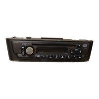
1. Main unit
-----------
1
PF-2945A-A
(Genuine No. 86201FG600)
(ID No. CZ601U1)
SPECIFICATIONS
Tuner section
Tuning system: PLL Frequeency synthesizer system
Receive range: AM
530kHz to 1710kHz
(10kHz steps)
FM 87.75MHz t o 107.9MHz
Intermediate frequency: AM 10.7 +0.03/-0.03MHz
FM 10.7 +0.03/-0.03MHz
Quieting sensitivity: AM Less than 39dBu
(at 20dB S/N)
FM Less than 15dBu
(at 30dB S/N)
Separation: FM More than 15dB
Auto stop sensitivity: AM 35 +6/-6dBu(DX)
55 +8/-8dBu(LO)
(PF-2945A-A)
41 +6/-6dBu(DX)
61 +8/-8dBu(LO)
(PF-2982B-A)
(600kHz, 1000kHz, 1400kHz)
FM 23 +6/-6dBu(DX)
(87.9MHz, 98.1MHz, 107.9MHz)
S/N ratio: AM More than 45dB
FM More than 50dB
CD section
Frequency Response: 17Hz to 20kHz
S/N ratio: More than 70dB (JIS-A)
Separation: More than 55dB (20kHz LPF)
MP3/WMA operations: MP3 Sampling rate 11.025kHz-48kHz,
Bit rate 8kbps-320kbps / VBR
WMA Bit rate 48kbps-192kbps
Logical format (File system);
ISO9660 level 1, 2 or JOLIET or Romeo
AUX section
Distortion: Less than 1.0% (20kHz LPF)
S/N ratio: More than 70dB (JIS-A)
Separation: More than 55dB (20kHz LPF)
General section
Load resistance: 4 ohm
Supply voltage: DC 13.2V
Negative ground
Max. power output: More than 16Wx4
Dimensions(mm): 205(W)x100(H)x157(D)
PF-2982B-A
(Genuine No. 86201SC600)
(ID No. CP603U1)
Weight: appro.1.75kg
Published by Service Dept.
Printed in P.R.C.
Clarion Co., Ltd.
7-2, Shintoshin, Chuo-Ku, Saitama-Shi, Saitama 330-0081, Japan
Service Dept.: 7-2, Shintoshin, Chuo-Ku, Saitama-Shi, Saitama 330-0081, Japan
Tel: +81-48-541-3747 FAX: +81-48-541-3804
298-6487-00
Sep. 2007 X
Question and Answer IconNeed help?

Do you have a question about the Clarion PF-2945A-A and is the answer not in the manual?

Clarion PF-2945A-A Specifications

General IconGeneral
BrandClarion
ModelPF-2945A-A
CategoryCar Receiver
LanguageEnglish

Summary

PRODUCT SPECIFICATIONS

Tuner & CD Specifications

Technical details for tuner reception and CD playback operations.

Audio & Operations Specs

Specifications for AUX input, MP3/WMA, general unit parameters, and audio output.

Component Listing

Lists the main component groups of the car stereo unit.

IMPORTANT NOTES AND CAUTIONS

General Notes

Important product notes, disclaimers, and media compatibility information.

Repair and Inspection Guidelines

Instructions and precautions for engineers performing repairs or inspections.

Safety Precautions

Essential safety warnings regarding operation, handling, and repairs.

ADJUSTMENTS AND IC EXPLANATION

Adjustment Procedure

Step-by-step guide for calibrating the unit's tuner and settings.

IC Pin Descriptions

Detailed function of each pin for the ICs used in the system.

SYSTEM BLOCK DIAGRAM

CD Mechanism Block Diagram

Visual representation of the CD mechanism's internal structure and connections.

MAIN SECTION OVERVIEW

Main PWB and Connectivity

Overview of the main Printed Wiring Board and its external connections.

EXPLODED VIEW AND PARTS LIST

Escutcheon Section Parts

Illustrated parts list for the unit's front panel assembly (Escutcheon).

MAIN SECTION PARTS LIST

Main PWB Components

Detailed list of parts mounted on the main Printed Wiring Board.

CD MECHANISM ASSEMBLY

CD Mechanism Exploded View

Detailed exploded view of the CD mechanism showing all parts.

ELECTRICAL PARTS LIST

Main PWB Electrical Components

Comprehensive list of electronic components for the Main PWB.

PRINTED WIRING BOARD SECTIONS

PWB Parts Lists

Parts lists for Switch, Sub, CD, and Sensor Printed Wiring Boards.

SYSTEM CONNECTIONS

Connector Pinouts and Overview

Details of Main, SIE-BUS, AUX connectors and system interconnection diagram.

PRINTED WIRING BOARD - SUB PWB(B3)

Sub PWB(B3) Layouts

Component and solder side layouts for the Sub PWB(B3).

PRINTED WIRING BOARD - MAIN PWB(B1) 1/7

Main PWB(B1) Layouts 1/7

Component and solder side layouts for the Main PWB(B1), part 1 of 7.

PRINTED WIRING BOARD - MAIN PWB(B1) 2/2

Main PWB(B1) Solder Side 2/2

Solder side layout for the Main PWB(B1), part 2 of 2.

PRINTED WIRING BOARD - SWITCH PWB(B2) 1/2

Switch PWB(B2) Component Side

Component side layout for the Switch PWB(B2), part 1 of 2.

PRINTED WIRING BOARD - SWITCH PWB(B2) 2/2

Switch PWB(B2) Solder Side

Solder side layout for the Switch PWB(B2), part 2 of 2.

CIRCUIT DIAGRAM - SUB PWB(B3)

Sub PWB(B3) Circuit Diagram

Schematic diagram illustrating the circuit of Sub PWB(B3).

CIRCUIT DIAGRAM - MAIN PWB(B1) 1/7

Main PWB(B1) Circuit Diagram 1/7

Schematic diagram of the Main PWB(B1), part 1 of 7.

CIRCUIT DIAGRAM - MAIN PWB(B1) 2/7

Main PWB(B1) Circuit Diagram 2/7

Schematic diagram of the Main PWB(B1), part 2 of 7.

CIRCUIT DIAGRAM - MAIN PWB(B1) 3/7

Main PWB(B1) Circuit Diagram 3/7

Schematic diagram of the Main PWB(B1), part 3 of 7.

CIRCUIT DIAGRAM - MAIN PWB(B1) 4/7

Main PWB(B1) Circuit Diagram 4/7

Schematic diagram of the Main PWB(B1), part 4 of 7.

CIRCUIT DIAGRAM - MAIN PWB(B1) 5/7

Main PWB(B1) Circuit Diagram 5/7

Schematic diagram of the Main PWB(B1), part 5 of 7.

CIRCUIT DIAGRAM - MAIN PWB(B1) 6/7

Main PWB(B1) Circuit Diagram 6/7

Schematic diagram of the Main PWB(B1), part 6 of 7.

CIRCUIT DIAGRAM - MAIN PWB(B1) 7/7

Main PWB(B1) Circuit Diagram 7/7

Schematic diagram of the Main PWB(B1), part 7 of 7.

CIRCUIT DIAGRAM - SWITCH PWB(B2)

Switch PWB(B2) Circuit Diagram

Schematic diagram illustrating the circuit of the Switch PWB(B2).

PRINTED WIRING BOARD - SENSOR/CD PWB

Sensor/CD PWB Layouts

Component and solder side layouts for Sensor and CD PWBs.

CIRCUIT DIAGRAM - SENSOR/CD PWB

Sensor/CD PWB Circuit Diagram

Schematic diagram illustrating the circuit of Sensor and CD PWBs.

Related product manuals