Do you have a question about the Clarion UNGO MS3001 and is the answer not in the manual?
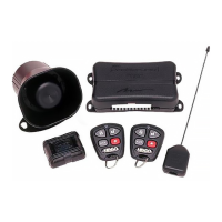
Proper placement and mounting methods for the main unit.
Guidance for mounting the MS3001 and MS3200 sirens.
Instructions for installing the EXT2 Extended Range Antenna.
Guidance for mounting the override switch and LED status indicator.
Detailed pin-out and connection guide for the 14-pin main harness.
Explanation of the 4-pin auxiliary harness functions and connections.
Description of other harnesses, including battery backup siren and extra LEDs.
Overview of jumper settings for various system functions like Auto Rearm and Polarity.
Procedure for accessing and physically setting the system's jumpers.
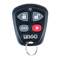
Details on the remote transmitter buttons, LED, and their basic operations.
Guide on using a single transmitter to control multiple vehicles.
Steps to add new transmitters and erase existing ones from the system.
How to choose between Passive and Active Arming modes.
Configuration for automatic door locking/unlocking with ignition status.
Procedure to reset all system parameters to factory defaults.
Instructions for enabling and disabling Valet Mode for temporary deactivation.
Interpreting siren chirps and LED flashes for tamper alerts and zone identification.
Guide to setting the shock sensor's primary trigger sensitivity levels.
How to adjust the shock sensor's warning impact sensitivity.
A chart for interpreting system chirp and LED flash codes.
Understanding how the system performs continuous diagnostics and reports issues.
Wiring diagrams for controlling the dome light using relays.
Details on using Auxiliary Function 2 for custom operations like audio system control.
Explanation of the DLRM's 5-pin and 3-pin harness connections and functions.
Steps for installing the DLRM and connecting it to the alarm system.
| Brand | Clarion |
|---|---|
| Model | UNGO MS3001 |
| Category | Car Alarm |
| Remote Control | Yes |
| Keyless Entry | Yes |
| Ignition Kill | Yes |
| Starter Disable | Yes |
| Door Lock Control | Yes |
| Trunk Release | Yes |
| Panic Mode | Yes |
| Valet Mode | Yes |
| Shock Sensor | Yes |
| Siren | Yes |