EasyManua.ls Logo

Clarion Ungo MS1001 User Manual

Clarion Ungo MS1001
10 pages
To Next Page IconTo Next Page
Page #1 background imageLoading...
Page #1 background image
Question and Answer IconNeed help?

Do you have a question about the Clarion Ungo MS1001 and is the answer not in the manual?

Clarion Ungo MS1001 Specifications

General IconGeneral
BrandClarion
ModelUngo MS1001
CategoryCar Alarm
LanguageEnglish

Summary

Pre-Installation Procedures

Setup, Verification, and Tips

Verify contents, consult owner, check systems, and follow installation best practices.

Mounting Components

Component Placement and Sensitivity

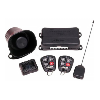
Mounting Shock Sensor and MS1001 Brain for optimal performance and sensitivity.

Jumper Configuration and Component Wiring

Jumper Settings and Component Placement

Configure jumpers and install Siren, Antenna, LED, and Override Switch.

System Programming Options

Arming Modes and Door Lock Control

Set Silent Arming, Arm Mode, and Ignition Controlled Door Locks.

Shock Sensor and System Modes

Shock Sensor Sensitivity Adjustment

Adjust shock sensor sensitivity through transmitter, 8 levels plus off.

System Reset and Valet Mode

Procedure for default reset and activation/deactivation of Valet Mode.

Jumper Selection and Functionality

Jumper Functions Overview

Details on jumpers for parking light polarity, auto rearm, sensor defeat, dome light, and door locks.

Wiring Diagram and Pinout

System Component Connections

Diagram shows Antenna, Override Switch, System LED, and main plugs.

14-Pin Harness Pinout

Detailed description of each pin's function on the main 14-pin harness.

Wiring Harness Description

14-Pin Main Harness Function

Detailed explanation of each wire's function on the 14-pin harness.

Starter Kill Output Connections

Description and diagram for connecting the Normally Closed Starter Kill output.

Advanced Wiring and Transmitter Setup

Starter Kill and Auxiliary Outputs

Details on Normally Open Starter Kill, Parking Lights, and Auxiliary outputs.

Adding and Erasing Transmitters

Procedures for adding new transmitters and erasing existing ones.

Door Lock Relay Diagrams

Door Lock Relay Configurations

Diagrams for Negative Trigger, Positive Trigger, Voltage Reversal, and Vacuum Lock Systems.

Related product manuals