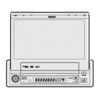
VRX765VD
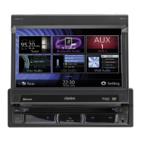
VRX766VD
- 8 -
9. Free run frequency adjustment
Input signal: 10-steps wave
Measurement is performed by composite screen display.
It measures by frequency counter and DIMMER is 100%.
9-1.Adjust VR941 so that the frequency of TP949 will be-
come to 15.734kHz+10/-10Hz.
*TP804 is made to short-circuit to GND. It checks that
the voltage of TP951 is 1.61+0.20/-0.20V at this time.
And checks that the voltage of TP952 is same.
10.PAL burst cleaning coil adjustment
Input signal:The color bar signal of PAL.
It measures with an oscilloscope etc.
10-1.Adjust L803 coil so that change TP860(LCD-B) of a
color waveform may be lost.
11.BRT/COL/HUE check
Input signal: Split color bar signal
11-1.Comfirm that the color bar is normally displayed at state
to begin.
11-2.Comfirm that the BRT/COL/HUE control is moved
screen.
11-3.Comfirm the superimposition display is normally.
12.V-MUTE check
Input signal:Split color bar signal
12-1.Comfirm a composite video screen is mute of V-
MUTE:"H" .
13.Wide mode check
Input signal:Split color bar signal
13-1. Comfirm a wide mode changed screen(Full wide /Wide
/Cinema /Normal).
14.Screen position check
Input signal: Mono-sucpeo signal.
14-1.Comfirm that the screen is displayed in the center by
mono-scope display (Video mode).
14-2.Comfirm that the screen is displayed in the center by
radio screen display (RGB mode).
15.Synchronicity condition check
15-1.Comfirm a normal display by DVD playback (main
menu) of HITOMI.
16.Key sw operation/Illum check
16-1Comfirm that key operation can be performed.
16-2Comfirm the key illum lighting .
17.Back light check
Power supply voltage: 13.2V
DIMMER=100%
17-1.Comfirm the TP962 freqency is 63kHz +5/-5kHz.
17-2.Comfirm the TP961 voltage is 5.2V +0.5/-0.5V.
17-3.Comfirm the light on at the power supply voltage to
10V.
17-4.Comfirm check at DIMMER control changes so that
brightness changes.
18.VCOM-DC check
Input signal:10-steps wave
Measurement is performed by composite screen display.
18-1.Adjust VR807(VCOM DC) so that a screen flicker may
become the minimum.
Main PWB section
19.TV delay time adjustment
Adjustment is performed in TV mode and the stable chan-
nel which does not have disorder in a screen is used.
It acts as the monitor of the signal of TP329 (Normal
horizontal synchronous input) and TP421 (Delay output
synchronization).
19-1.To falling of the Horizontal Synchronizing signal of
TP329, VR401 is adjusted so that falling of TP421 may
be overdue 3.50 +0.1/-0.1 uS
19-2.Confirm that Low level time of TP421 is 4.7 +0.7/-0.7uS.
19-3.It checks whether there is any gap in the right-and-left
balance of a superimposition display to TV image, or the
character has not passed by the end after the adjust-
ment.
Recommends connected TV tuner :TTX7501Z(ZT-
4620B-A) for NTSC,:TTX7504Z(ZT-4610K-A) for PAL(s).
20.S-meter adjustment of BUS-tuner
The adjustment data is written in the memory of
EEPROM(IC502).The special jig and software are nec-
essary for BUS-TUNER adjustment.
* CeNET-analyzer
* Windows installed Personal computer
* SSG
* Adjustment-Software(Ver.Y4-S009-513-20051111)
a. Installation of software in the set-folder of the writing
E2P.
b Connect CeNET-analyzer to the unit with the CeNET-
cable.
c Connect CeNET-analyzer(MASTER/SLAVE side) to the
PC with the serial crossing cable.
d Connect POWER-lead of CeNET-analyzer to the
POWER-lead of the unit.
e Connect the antenna to the unit.(FM-ANT for first ad-
justment)
f Turn on CeNET-analyzer,and press the RESET-button
of it.
20-1.Set up the software
20-1-1.Click [ADJ_DSP].
20-1-2.Click [open Comm PORT].(To open the COM port
of PC)
20-1-3.Click [Initialization of JIG].(The BUS-analyzer
sounds)
20-1-4.Click [Incoming connection].(The unit is recognized
to the BUS-analyzer)
The data is displayed, and the display changes regu-
larly.
20-2.PRN data writing / Set up FM-IF-Offset data
20-2-1.Click [Initial EEPROM with CS 16], and select PRN-
FILE.
The PRN-data is write in EEP-ROM of the unit.
20-2-2.Confirm "OK" display after writing of data.
20-2-3.Click [Setting-prn] under "FM IF-COUNT".(the writ-
ten FM-IF-Offset data becomes effective.)
20-3.Adjustments FM S-meter
20-3-1.Set SG output to 65dBuV.(FM)
20-3-2.Click [Adj,HI] of "FM S-Meter".(Wait until the value
stops.)
 Loading...