5
General Function Explanation
Sensitivity Control (Gain)
This adjustment is provided to adjust the amplier sensitivity so that it will produce
maximum power given a variety of different input signal voltages. Setting this correctly will
ensure that you get maximum performance from your amplier and is critical to ensuring
that minimal noise and distortion is produced.
Clarion recommends the use of an Oscilloscope or distortion detecting device such as the
SMD DD-1 or DD-1+ Distortion Detector to properly set amplier sensitivity. A headroom
(gain overlap) setting of 10dB will help to ensure that music that is recorded at low levels
can still be reproduced at high volume levels. With this setting, it is the responsibility of the
operator to use the amplier in a manner that will not produce audible distortion. If the end
user does not understand why 10dB of gain overlap has been used, please use a lower
overlap, 5dB or 0dB to ensure proper system protection.
Procedure (Oscilloscope) Method:
1. Obtain a test disc with a selection of Sine Waves recorded at different levels (-10, -5
and 0dB).
2. Turn the gain all the way down on the amplier (to the left).
3. Connect the ground terminal of the scope lead to the shield of the RCA cable coming
from the source unit. Do no connect this to the speaker output terminals.
4. Connect the scope probe to a speaker terminal on the channel you want to adjust.
5. Select a Sine wave frequency that is well away from the chosen crossover frequency.
For midrange speakers use 1kHz, use 40Hz for subwoofers.
6. Turn the source unit up as high as possible without distortion.
7. Monitor the output waveform of the amp on the scope.
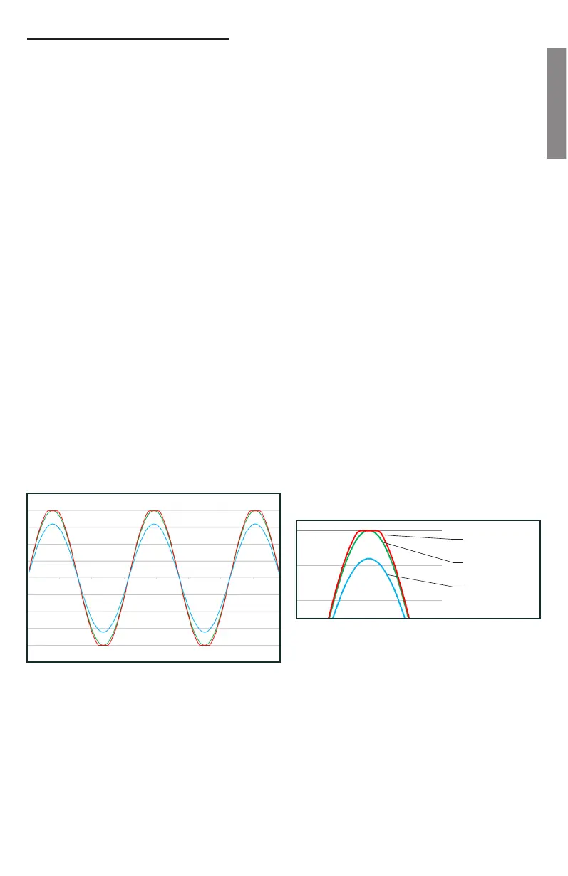
8. Increase the sensitivity of the amplier until the scope waveform shows a small at
spot on the top or bottom of the waveform. See Figure 2 for an example of what to
look for.
SMD Distortion Detector Method:
1. Following the instructions provided with the DD-1 or DD-1+, use the 0dB track to
conrm the output of the source unit is unclipped.
2. Connect the Distortion Detector to the output of the amplier and use an appropriate
-10dB track. Increase the gain on the amplier until the Distortion LED illuminates
You should be able to turn the volume up to almost full volume without hearing distortion
from your amplier. If you can’t turn the volume up most of the way without distortion, the
gains are not set properly.
Sine wave unclipped
Clipped Sine wave
Sine wave well bellow clipping
Fig 1 - Sine Wave at different Levels
Fig 2 - Close-Up of waveforms
 Loading...