EasyManua.ls Logo

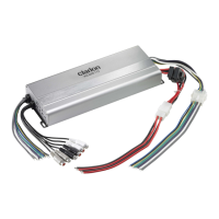
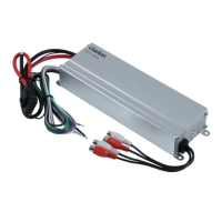
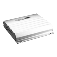
Clarion XC6620

Clarion XC6620
40 pages
To Next Page IconTo Next Page
Loading...
Owner’s manual & Installation manual
Mode d’emploi at manuel d’installation
XC6420
XC6620
XC6 Series Ampli ers
Ampli cateurs XC6

Questions and Answers:

Clarion XC6620 Specifications

General IconGeneral
BrandClarion
ModelXC6620
CategoryAmplifier
LanguageEnglish

Summary

ABOUT THE MANUAL AND WARRANTY

FEATURES

WARNING

XC6420 CONNECTIONS AND CONTROLS

Channel 1&2 Mode Select Switch

Selects the operating mode for channels 1 and 2 (e.g., Stereo, Mono, Bridged).

Channel 3&4 Mode Select Switch

Selects the operating mode for channels 3 and 4 (e.g., Stereo, Mono, Bridged).

Channel 1&2 Input Sensitivity Control (Gain)

Adjusts the input signal level for channels 1 and 2 to match the source unit.

Input Selection Switch

Determines how input signals are routed to the amplifier's channels.

Channel 3&4 Input Sensitivity Control (Gain)

Adjusts the input signal level for channels 3 and 4 to match the source unit.

Channel 1 Input RCA Connection

RCA input for channel 1 signal.

Channel 3 Input RCA Connection

RCA input for channel 3 signal.

Channel 1 Auto Sensing Control switch

Enables automatic turn-on when it detects an audio signal.

Channel 1&2 Bass Boost Level Control

Adjusts bass boost level for channels 1 and 2.

Channel 1&2 Crossover Frequency Control

Sets the cutoff frequency for the crossover on channels 1 and 2.

Channel 1&2 Crossover Function Switch

Selects the crossover type (HPF, LPF, Full Range) for channels 1 and 2.

Channel 3&4 Crossover Frequency Control

Sets the cutoff frequency for the crossover on channels 3 and 4.

Channel 3&4 Crossover Frequency Multiplier Control Switch

Multiplies the crossover frequency range for channels 3 and 4.

Channel 3&4 Crossover Function Switch

Selects the crossover type (HPF, LPF, Full Range) for channels 3 and 4.

Slot for remote level control wire

Connection point for the optional remote subwoofer level control.

Two 30 A Fuses

Main fuses for power protection.

+12 V Constant Power Source

Main power input connection.

Remote Turn-On Connection

Connection for the remote turn-on lead from the head unit.

Ground Connection

Main ground connection point for the amplifier.

Channel 2 Input RCA Connection

RCA input for channel 2 signal.

Channel 4 Input RCA Connection

RCA input for channel 4 signal.

Channel 1&2 Speaker Connections

Speaker output terminals for channels 1 and 2.

Channel 3&4 Speaker Connections

Speaker output terminals for channels 3 and 4.

XC6620 CONNECTIONS AND CONTROLS

Input Selection Switch

Determines how input signals are routed to the amplifier's channels.

Channel 1 Auto Sensing Control switch

Enables automatic turn-on when it detects an audio signal.

Channel 5&6 Bass Boost Control Switch

Adjusts bass boost level for channels 5 and 6.

Channel 1 Input RCA Connection

RCA input for channel 1 signal.

Channel 3 Input RCA Connection

RCA input for channel 3 signal.

Channel 5 Input RCA Connection

RCA input for channel 5 signal.

Channel 1&2 Crossover Frequency Control

Sets the cutoff frequency for the crossover on channels 1 and 2.

Channel 1&2 Crossover Function Switch

Selects the crossover type (HPF, LPF, Full Range) for channels 1 and 2.

Channel 1&2 Input Sensitivity Control (Gain)

Adjusts the input signal level for channels 1 and 2 to match the source unit.

Channel 3&4 Crossover Frequency Control

Sets the cutoff frequency for the crossover on channels 3 and 4.

Channel 3&4 Crossover Function Switch

Selects the crossover type (HPF, LPF, Full Range) for channels 3 and 4.

Channel 3&4 Input Sensitivity Control (Gain)

Adjusts the input signal level for channels 3 and 4 to match the source unit.

Channel 5&6 Crossover Frequency Control

Sets the cutoff frequency for the crossover on channels 5 and 6.

Channel 5&6 Crossover Function Switch

Selects the crossover type (HPF, LPF, Full Range) for channels 5 and 6.

Channel 5&6 Input Sensitivity Control (Gain)

Adjusts the input signal level for channels 5 and 6 to match the source unit.

Slot for remote level control wire

Connection point for the optional remote subwoofer level control.

Two 35 A Fuses

Main fuses for power protection.

+12 V Constant Power Source

Main power input connection.

Remote Turn-On Connection

Connection for the remote turn-on lead from the head unit.

Ground Connection

Main ground connection point for the amplifier.

Channel 2 Input RCA Connection

RCA input for channel 2 signal.

Channel 4 Input RCA Connection

RCA input for channel 4 signal.

Channel 6 Input RCA Connection

RCA input for channel 6 signal.

Channel 1&2 Speaker Connections

Speaker output terminals for channels 1 and 2.

Channel 3&4 Speaker Connections

Speaker output terminals for channels 3 and 4.

Channel 5&6 Speaker Connections

Speaker output terminals for channels 5 and 6.

INSTALLATION PLANNING AND CONSIDERATIONS

General Function Explanation

Sensitivity Control (Gain)

Adjusts amplifier sensitivity for optimal performance and to minimize noise and distortion.

Procedure (Oscilloscope) Method

Step-by-step guide for setting amplifier gain using an oscilloscope.

SMD DD-1 Method

Instructions for setting amplifier gain using the SMD DD-1 distortion detector.

General Function Explanation Cont

Auto Sensing Control Switch

Enables automatic turn-on without REM terminal connection.

Bass Boost Level Control

Adds up to 12dB boost at 45Hz to enhance bass impact.

Crossover Function Switch

Selects the crossover mode (high-pass, low-pass, or off) for speaker protection.

Crossover Frequency Control

Adjusts the -3dB crossover frequency from 50Hz to 500Hz (or 500-5000Hz with multiplier).

Remote Turn-On Connection

Activates the amplifier when +12V is applied to this terminal.

Speaker Connections

Details on connecting speakers for stereo and bridged modes, including impedance requirements.

Input RCA Connections

Instructions for connecting RCA pre-amp outputs or using adapters for speaker-level inputs.

Speaker Wiring Diagrams

4 Ohm Stereo (XC6420 or XC6620)

Wiring diagram for connecting four 4-ohm speakers in stereo mode.

2 Ohm Stereo (XC6420 or XC6620)

Wiring diagram for connecting four 2-ohm speakers in stereo mode.

Speaker Wiring Diagrams Cont

4 Ohm Mono - One 4 Ohm Single Voice Coil Subwoofer

Wiring diagram for a single 4-ohm subwoofer in mono bridged mode.

4 Ohm Mono - One Dual 2 Ohm Voice Coil Subwoofer

Wiring diagram for a dual 2-ohm voice coil subwoofer in mono bridged mode.

Speaker Wiring Diagrams Cont

4 Ohm Mono - Two Dual 4 Ohm Voice Coil Subwoofers

Wiring diagram for two dual 2-ohm voice coil subwoofers in mono bridged mode.

Signal Distribution

Signal Distribution Cont

XC6420 Input Selection Switch

Describes XC6420 input routing for 4 Channel, 2 Channel, and 2 Channel Bass Boost modes.

XC6420 Mode Select Switch

Explains Stereo, Mono, and Bridged modes for XC6420 channel pairs.

XC6620 Input Selection Switch

Details input routing for XC6620 in 6 Channel, 4 Channel, and 2 Channel modes.

XC6420 Signal Distribution Flow Chart

XC6620 Signal Distribution Flow Chart

Power Connections

Wiring Precautions

Installation

Subwoofer Level Control Installation

TROUBLESHOOTING

Specifications

XC6420

Technical specifications for the XC6420 amplifier, including power output and frequency response.

Specifications

XC6620

Technical specifications for the XC6620 amplifier, including power output and frequency response.

Related product manuals