EasyManua.ls Logo

Clarke Metalworker CDP501F - User Manual

Clarke Metalworker CDP501F
23 pages
Print Icon
To Next Page IconTo Next Page
Loading...
1
SERIAL No.................... 0307

Questions and Answers

  • S
    shepherdmichaelJul 31, 2025
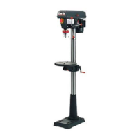
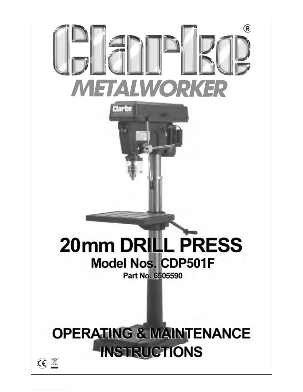
    What to do if my Clarke Metalworker CDP501F Power Tool motor won't start?
    • M
      Ms. Marissa CalderonAug 1, 2025
      If your Clarke Power Tool motor won’t start, there are several potential causes. First, check the power cord and fuse. Then, inspect the motor and switch connections. If the switch is faulty, it should be replaced. Also, ensure the pulley cover is closed properly. Burnt motor windings will require motor replacement.
  • D
    Desiree FreemanAug 8, 2025
    Why is my Clarke Metalworker CDP501F making a noisy operation under load?
    • A
      Alice HernandezAug 8, 2025
      Noisy operation of your Clarke Power Tool under load can be due to several factors. You may need to adjust the belt tension, lubricate a dry spindle by removing the spindle/quill assembly, or tighten a loose pulley. A worn bearing may also be the cause, in which case it should be replaced.
  • J
    James WebsterAug 14, 2025
    How to fix excessive drill wobble in Clarke Metalworker CDP501F Power Tool?
    • J
      Joshua ClarkAug 14, 2025
      Excessive drill wobble in your Clarke Power Tool can stem from a few issues. Start by tightening the chuck by pressing it down onto a block of wood against the table. If that doesn't solve the problem, the spindle, bearing, or chuck might be worn and need replacement. Also, check if the drill is bent and renew if necessary.
  • T
    Timothy JonesAug 22, 2025
    What to do if Clarke Metalworker CDP501F drill binds in workpiece?
    • A
      amberescobarAug 22, 2025
      If the drill binds in the workpiece while using your Clarke Power Tool, it could be due to excessive feed pressure—try applying less pressure. Ensure the belt is properly tensioned and the drill is tightened with the key. Also, verify that the drill speed is correct by referring to the cutting speed chart.

Summary

Product Information

Declaration of Conformity

Statement confirming the product complies with relevant standards and directives.

Introduction

Welcome message and overview of the drill press.

Guarantee Information

Details regarding the manufacturer's warranty and conditions.

Safety Guidelines

General Safety Precautions

Key safety rules for operating machinery to prevent injury and damage.

Additional Safety Rules for Drill Presses

Specific safety guidelines tailored for the drill press operation.

Setup and Preparation

Electrical Connections

Guidelines for connecting the drill press to a power supply.

Wiring Diagram

Illustrates the electrical connections for the drill press motor and switches.

Preparation and Unpacking

Procedures for unpacking, checking parts, and preparing the machine.

Assembly Instructions

Column Assembly to Base

Attaching the column assembly to the base using provided screws.

Mounting the Table Assembly

Installing the table, crank, and rack onto the column assembly.

Head to Column Mounting

Securing the head assembly onto the column.

Chuck Guard Assembly

Installing the chuck guard onto the quill shaft.

Installing the Chuck

Attaching the chuck to the spindle arbour.

Fitting the Drive Belts

Adjusting belt tension and fitting belts for speed selection.

Microswitch Operation Check

Ensuring the pulley cover microswitch functions correctly for safety.

Pulley Cover Knob Installation

Attaching the knob to the pulley cover.

Operation and Adjustment

Description of Parts

Identification and description of the main components of the drill press.

Table Adjustment

Adjusting table height, swivel, and tilt for drilling operations.

Spindle Depth Setting

Setting the drilling depth using the depth stop collar.

Changing Drill Speed

Adjusting belt positions to select the correct spindle speed.

Operation Procedures

Step-by-step instructions for using the drill press safely and effectively.

Maintenance and Support

Removing the Chuck

Procedure for safely detaching the chuck from the spindle.

Maintenance Schedule

Regular tasks for keeping the drill press in optimal condition.

Trouble Shooting Guide

Diagnosing and resolving common problems encountered with the drill press.

Spare Parts and Servicing Information

Contact details and information for obtaining spare parts and service.

Component Diagrams

Head Assembly Diagram

Diagram illustrating the components of the drill press head assembly.

Base Assembly Diagram

Diagram illustrating the components of the drill press base assembly.

Pulley Cover Diagram

Diagram illustrating the components of the drill press pulley cover.

Quill Assembly Diagram

Diagram illustrating the components of the drill press quill assembly.

Technical Specifications

Specifications

Technical details and measurements of the drill press.

Optional Accessories

List of available optional accessories for the drill press.

Clarke Metalworker CDP501F Specifications

Motor Specifications IconMotor Specifications
motor voltage230 V
motor frequency50 Hz
motor phase1 Ph
Power and Current IconPower and Current
power rating980 Watts
current rating4.3 Amps
fuse rating13 Amp
Speed IconSpeed
speed1400 RPM
number of drill speeds12
speed range120 - 2, 700 RPM
Table and Dimensions IconTable and Dimensions
table dimensions425 x 475 mm
table T-slot dimensions15 x 355 mm x 3
overall dimensions1680 x 575 x 850 mm
Maximum Distances and Diameters IconMaximum Distances and Diameters
max spindle travel120 mm
max distance chuck to table706 mm
max distance chuck to base1095 mm
Belt and Weight IconBelt and Weight
belt type A1 x A33 - 838
belt type B1 x A29 - 737
weight150 kg

Related product manuals