5
Parts & Service: 020 8988 7400 / E-mail: Parts@clarkeinternational.com or Service@clarkeinternational.com
IMPORTANT: The wires in the mains lead are coloured in accordance with
the following code:
Green & Yellow .......... Earth
Blue .......... Neutral
Brown .......... Live
As the colours of the flexible cable of this appliance may not correspond with
the coloured markings identifying terminals in your plug, proceed as follows:
• Connect GREEN & YELLOW wire to plug terminal marked with a letter “E”
or Earth symbol “ ”, or coloured GREEN or GREEN & YELLOW.
• Connect BROWN wire to plug terminal marked letter “L” or coloured
RED.
• Connect BLUE wire to plug terminal marked letter “N” or coloured
BLACK.
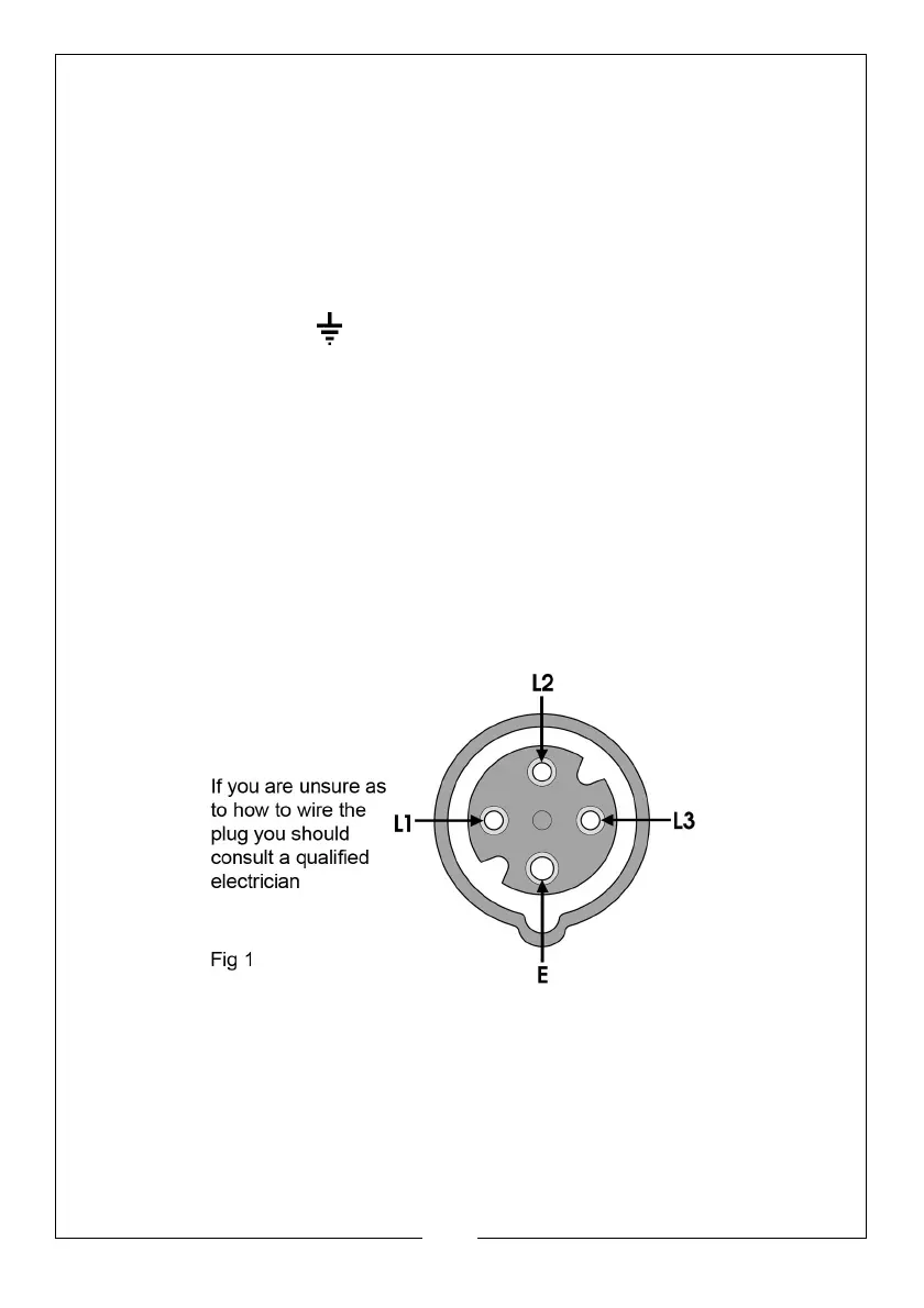
CONNECTING THE OUTPUT
The output is plugged into the socket (E, Fig. 2), using a 4-pin -plug (not
provided). The illustration below shows the socket configuration.
This unit requires a 16A, 400V (3-pin+ earth) plug which should be wired
ensuring pins L1 and L3 are used for the connections across the motor
windings;- i.e. these are the ‘hot phases’.