9 8
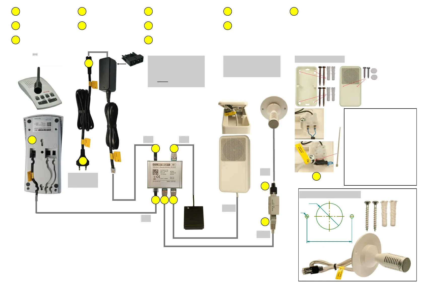
Control Room
Intercom system
with footswitch
2m
3m
2m 2
2a
1b
4a
3b
5
> Intercom Power Supply
< Intercom Cleaner Socket
> Intercom Connecon Hub (6)
(DC Power)
< Intercom Power Supply
15V /700mA
> Intercom Cleaner Socket
< Intercom Power Supply
> Intercom Connecon Hub (1)
< Intercom Console (1)
> Intercom Console (1)
< Intercom Connecon Hub (1)
1
1a
1b
2
2a
> Intercom RJ45 Connector (1)
< Intercom Microphone
3
> Intercom R45 Connector (2)
< Intercom Connecon Hub (2)
3a
> Intercom Connecon Hub (2)
< Intercom R45 Connector (2)
3b
Wandsteckdose
100-240V
50-60Hz
~
wall socket
100-240V
50-60Hz
~
No other power supply than the one tested and appro-
ved by Clarson must be used.
1a
1
4
H
C
C
N
Installaon Loudspeaker
Paent´s Room
20m
20m
1m
3
3a
> Intercom Speaker
< Intercom Connecon Hub (3)
> Intercom Connecon Hub (3)
< Intercom Speaker
4
4a
Ceiling installaon microphone
drilling template
J
Important for Installaon Planning:
Dimensions microphone cable :
Length 1m, Ø 3,1mm
Extension cable length 20m, Ø 5,5mm
Clearance hole for RJ45 connector
minimum Ø16mm.
Observe drilling template!
Dimensions loudspeaker cable:
Length 20m, Ø 5,5mm
Clearance hole for RJ45 connector
minimum Ø17mm.
Dimensions mounng material
see page 4
> Intercom Connecon Hub (4)
< Footswitch (4)
5
 Loading...