5
GLOW UP
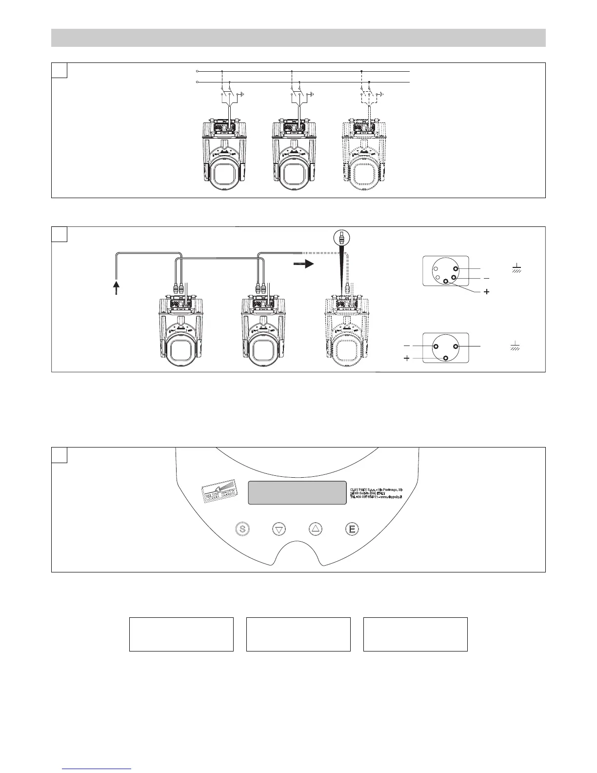
Switching on the projector - Fig. 6
The projector immediately turns on when the power cord is plugged in or, if used in battery mode, by pressing and holding down keys
A
and
S
for
several seconds.
Clay Paky GLOW UP Address xxx BAT xx%
GLOW UP Software release x.x x xxxxx ??? *
The control panel (Figure 8) has a display and buttons for complete programming and management of the projector menu.
The display can be in one of two conditions: idle status and settings status.
When idle, the projector DMX address and percent battery charge are displayed.
If no button is pressed after a wait period (about 60 seconds) when in menu settings status, the display automatically returns to idle status. It should
be noted that when this condition occurs, any modified value that has not yet been confirmed with the
A
key will be cancelled.
To turn off the GlowUP, hold down keys
A
and
S
for several seconds. A confirmation message will appear (Switch off?).
Press
A
-Yes to turn off the GlowUP or press
S
-NO to return to the settings menu.
C
ONTROL PANEL
Connections to the control signal line (DMX) - Fig. 5
Use a cable conforming to specifications EIA RS-485: 2-pole twisted, shielded, 120Ω characteristic impedance, 22-24 AWG, low capacity. Do not use
microphone cable or other cable with characteristics differing from those specified. End connections must be made using XLR type 3 or 5-pin male/female
connectors. A terminating plug must be inserted on the last projector with a resistance of 120 Ω (minimum 1/4 W) between terminals 2 and 3.
IMPORTANT: The wires must not make contact with each other or with the metal casing of the connectors. The casing must be connected to the shield
braid and pin 1 of the connectors.
* see pag. 5
Display symbology