CB780E/CB784E RELAY MODULES WITH VALVE PROVING
750-234 19 32-00150—03
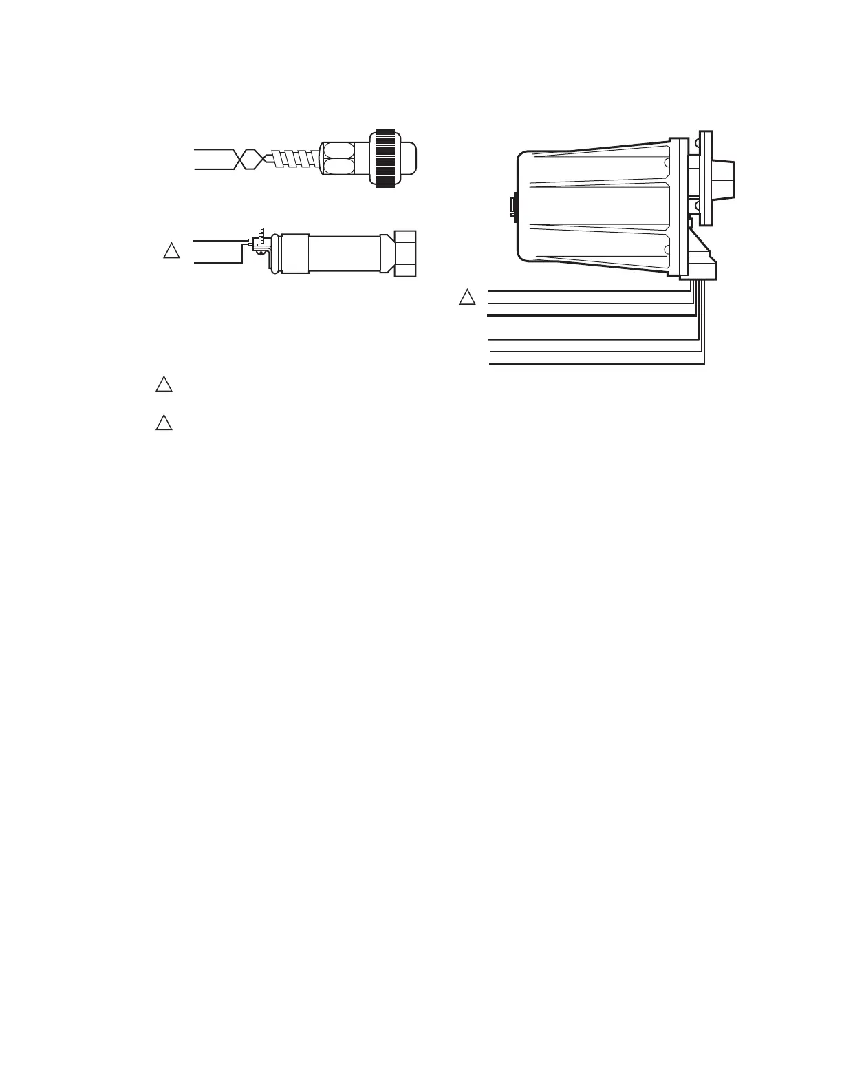
Fig. 20. Flame detector wiring.
VALVE PROVING SYSTEM
The Valve Proving System feature provides a systematic
way of testing the valve seat integrity to assure the valves
are in the closed state whenever the sequence of
operation requires them to be closed. It is designed to
detect a leak greater than 0.1% of the burner input
capacity. For example, a 10 million Btu/hr natural gas-
fueled burner would have a fuel input capacity of
approximately 1,000 ft
3
/hr. A leak rate greater than 0.1%
of 1,000 ft
3
/hr or 1 ft
3
/hr in either valve will be detected
with the Valve Proving System. Smaller leaks will not be
detected.
At commissioning time, the Valve Proving System may be
scheduled to occur at one of five different times: Never,
Before, After, Both, and Split.
Never—Device default as received: in this case Valve
Proving does not occur.
Before—Valve Proving occurs concurrently with Pre-
Purge.
After—Valve Proving occurs after the Run state before
the internal Safety Relay dropout state and concurrent
with Post Purge (if configured).
Both—Valve proving occurs at both times Before and
After noted above.
Split—The downstream seat (high pressure) test is per-
formed at the Before time and the upstream seat (low
pressure) test is performed during the After time.
The Valve Proving items programmed are:
1. Specify when to perform Valve Proving. Demand
input to terminal 17 actually enables the function of
Valve
Proving.
2. Specify the time duration of the test (calculated from
Appendix A).
BLUE
YELLOW
WHITE
WHITE
BLACK
BLACK
F
G
22
L2
L1
L2
M28588A
BLUE
WHITE
BLUE
WHITE
F
G
F
G
INFRARED (817-4133)
ULTRAVIOLET (817-1743)
SOLID STATE SELF-CHECKING
ULTRAVIOLET (817-1121)
1
2
1
FLAME DETECTOR LEADS ARE COLOR CODED. THE BLUE LEAD MUST BE CONNECTED TO THE F TERMINAL AND THE WHITE
MUST BE CONNECTED TO THE G TERMINAL. THE UV SENSING TUBE IS POLARITY SENSITIVE. REVERSING THE LEADS EVEN
MOMENTARILY CAN DAMAGE OR DESTROY THE UV TUBE.
FLAME DETECTOR LEADS ARE COLOR CODED. THE BLUE LEAD MUST BE CONNECTED TO THE F TERMINAL AND THE YELLOW
MUST BE CONNECTED TO THE G TERMINAL. THE UV SENSING TUBE IS POLARITY SENSITIVE. REVERSING THE LEADS EVEN
MOMENTARILY CAN DAMAGE OR DESTROY THE UV TUBE.
2