Do you have a question about the CleaverBrooks CB780E and is the answer not in the manual?
Microprocessor-based integrated burner control for automatically fired gas, oil, or combination fuel...
Valve Proving System can be scheduled to occur at one of five different times: Never, Before, After, Both, Split.
Includes safety interlock, closed loop logic test, dynamic AMPLI-CHECK™, dynamic input check, etc.
Covers voltage checks, communication, reliability, and diagnostics via VFD display.
Details voltage, frequency, power dissipation, and fusing requirements.
Details conditions under which safety shutdown occurs during various operational periods.
Checks purge card integrity, configuration jumpers, and internal hardware. POWER LED blinks for checks.
Verifies safety critical loads and terminal energization, preventing nuisance shutdowns.
Includes Ampli-Check, flame amplifier, input, safety relay, self-check, safe-start, and switch tests.
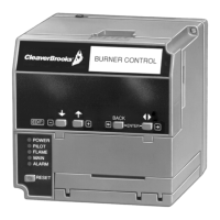
LEDs provide visual indication of program sequence: POWER, PILOT, FLAME, MAIN, ALARM.
Shows sequence timing, diagnostics, historical info, and annunciator info for troubleshooting.
Reports shutdown causes and distinguishes between field and internal system problems.
Defines Low Fire, High Fire, and Lockout Interlock functions and requirements.
Input typically connected to proof-of-closure switches; must be energized throughout PREPURGE.
Covers environmental limits for humidity (max 85% RH) and vibration (max 0.5G).
Device is not weather tight; requires protection for outdoor installation.
Instructions for mounting the wiring subbase, avoiding horizontal orientation with contacts down.
Covers subbase/remote wiring, power disconnection, code compliance, and wire selection.
Mount vertically or horizontally in an electrical enclosure, allowing clearance for components.
Align interlocking ears, insert, and push to secure module to the relay module.
Align interlocking ears, insert, and push to secure module to the relay module.
Mount on panel door or remote locations, following instructions for clearance and drilling.
Tests valve seat integrity to detect leaks >0.1% of burner capacity.
System can be scheduled for Never, Before, After, Both, and Split at commissioning.
Specify when to perform, and the time duration for the Valve Proving test.
Monitors pressure between shutoff valves (MV1, MV2) to detect leaks, operating via sequence A-F.
Guides selection of Honeywell pressure switches based on operating range and pressure.
Refer to instructions for installation and adjustment of C6097A Pressure Switch.
Sets up when Valve Proving test occurs: Never, Before, After, Both, or Split.
Sets up the duration for the Valve Proving Test.
Details three jumper options (JR1, JR2, JR3) for configuring pilot flame, DSI, and interlock checks.
Lists recommended equipment for static checkout, including voltmeter and jumper wires.
Provides general guidelines for performing static checkout tests.
Describes the burner sequence: Initiate, Standby, Pre-Purge, Ignition Trials, Run, Postpurge.
Sequence starts upon power-up; lasts ten seconds unless voltage/frequency tolerances are not met.
Control is ready to start sequence when operating control determines a call for heat.
Purge timers provide selectable timings; blower motor starts, firing rate motor drives to high fire.
Covers pilot flame and main flame establishment, including VP and DSI systems.
Used to scroll through selectable messages; wraps around when end is reached.
Changes selectable message levels, from main to subset or vice-versa.
Switches display from second-line selectable to preempted/lockout message.
Lists recommended equipment for static checkout, including voltmeter and jumper wires.
Lists various tests to perform, including preliminary inspection, flame signal, lightoff, and safety shutdown.
Tests if hot refractory masks flame signal; corrects issue by adjusting detector sighting or orifice.
Ensures ignition spark does not actuate FLAME LED; checks signal is <0.5 Vdc.
Checks detector response to artificial light and tests Flame Failure Response Time (FFRT).
Measures flame signal at max temperature; checks signal stability and response.
Performs tests after checkout to ensure safety shutdown functions correctly.
Checks fault code and shutdown on Preignition Interlock opening during STANDBY or PREPURGE.
Checks fault code and shutdown on Lockout Interlock opening during PREPURGE, PILOT IGN, MAIN IGN or RUN.
Covers issues like premature flame detection, pilot/main ignition failure, and loss of flame during RUN.
Checks fault code and safety shutdown if pilot fails to ignite.
Checks fault code and safety shutdown if main burner fails to ignite.
Checks fault code and shutdown on Preignition Interlock opening after POSTPURGE starts.
Identifies faults via Power LED blink codes and provides troubleshooting steps.
Recommends securing the device in an enclosed cabinet and protecting wiring.
Index of diagnostic information available on KDM, including terminal status, device type, and software revision.
Nonvolatile memory retains historical data for six most recent lockouts, including fault details.
Provides a systematic way to test valve seat integrity to ensure valves are closed when system is offline.
| Model | CB780E |
|---|---|
| Input Voltage | 120/240 VAC |
| Frequency | 50/60 Hz |
| Display | LCD |
| Manufacturer | Cleaver-Brooks |
| Operating Temperature | 0 to 50°C (32 to 122°F) |
| Communication Protocol | Modbus |