CB780E/CB784E RELAY MODULES WITH VALVE PROVING
32-00150—03 24 750-234
SETTINGS AND
ADJUSTMENTS
Selectable Site-Configurable
Jumpers
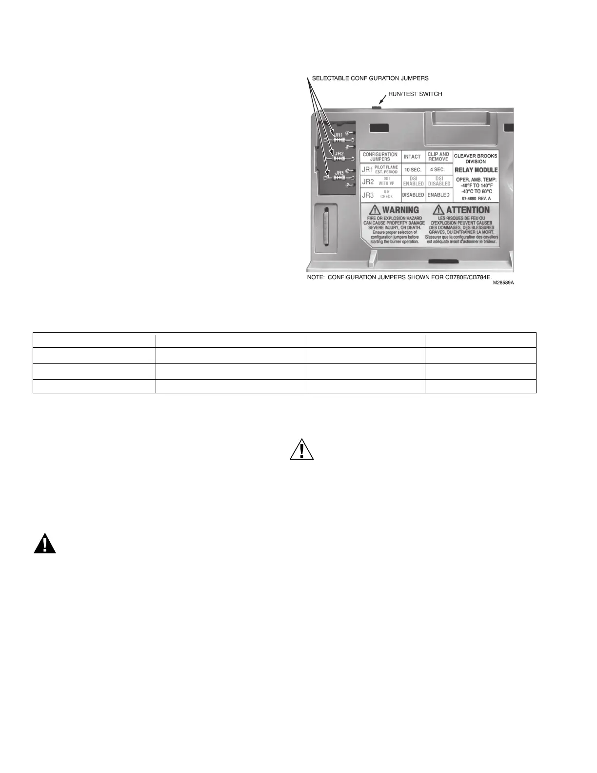
The CB780E/CB784E has three site-configurable jumper
options, see Fig. 39 and Table 7. If necessary, clip the site-
configurable jumpers with side cutters and remove the
resistors from the Relay Module.
Fig. 39. Selectable site-configurable jumpers.
a
DSI Enabled allows for Valve Proving test to be performed, then during PFEP both terminals 9 and 21 energize to light
the Main Flame. NOTE: PFEP will not occur and MFEP will automatically be 4 seconds, regardless.
STATIC CHECKOUT
After checking all wiring, perform this checkout before
installing the CB780E/CB784E on the subbase. These
tests verify the Q7800 Wiring Subbase is wired correctly,
and the external controllers, limits, interlocks, actuators,
valves, transformers, motors and other devices are
operating properly.
Explosion and Electrical Shock Hazard.
Can cause serious injury, death or equipment
damage.
1. Close all manual fuel shutoff valve(s) before
starting these tests.
2. Use extreme care while testing the system. Line
voltage is present on most terminal connections
when power is on.
3. Open the master switch before installing or
removing a jumper on the subbase.
4. Before continuing to the next test, be sure to
remove test jumper(s) used in the previous test.
5. Replace all limits and interlocks that are not
operating properly. Do not bypass limits and
interlocks.
Equipment Damage Hazard.
Improper testing can damage equipment.
Internal surge protectors can break down and
conduct a current, causing the CB780E/CB784E
to fail the dielectric test or possibly destroy the
internal lightning and high current protection. Do
not perform a dielectric test with the
CB780E/CB784E installed.
Equipment Recommended
1. Voltmeter (1M ohm/volt minimum sensitivity) set on
the 0-300 Vac scale.
2. Two jumper wires; no. 14 wire, insulated, 12 inches
(304.8 mm) long with insulated alligator clips at
both ends.
3. Ammeter can be used to verify valve loads con-
nected to the wiring subbase.
General Instructions
1. Perform all applicable tests listed in Static Checkout,
Table 8, in the order listed.
2. Make sure all manual fuel shutoff valve(s) are
closed.
Table 7. Site Configurable Jumper Options
Jumper Number Description Intact Clipped
JR1
Pilot Flame Establishing Period
a
10 seconds 4 seconds
JR2
DSI with Valve Proving
a
Enabled Disabled
JR3 Start-Up Interlock Check Disabled Enabled