CB780E/CB784E RELAY MODULES WITH VALVE PROVING
32-00150—03 2 750-234
The following assumptions apply when using the
CB780E/CB784E:
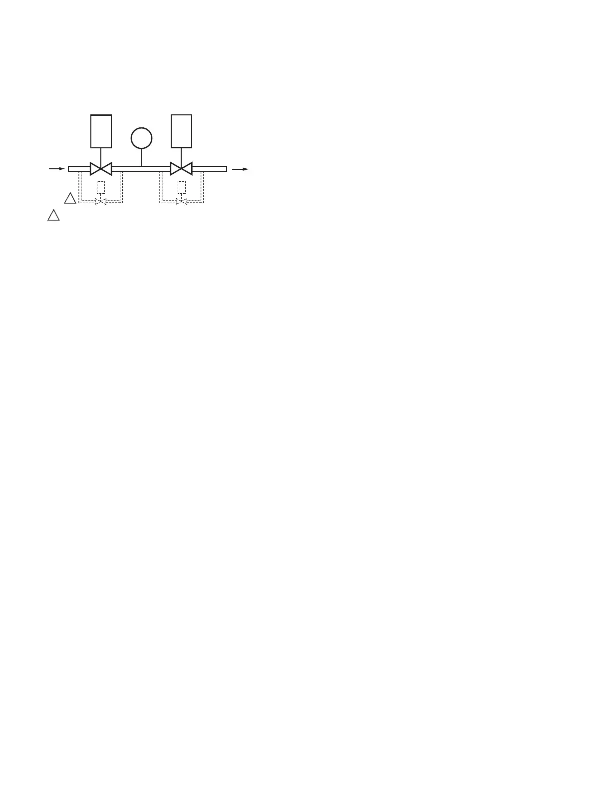
Fig. 1. The valve proving system.
MV1—Wired to terminal 9. It is located in the most
upstream position of the main gas valve train.
VPS—Valve Proving Switch: Setpoint at 1/2 of Main Valve
inlet pressure.
MV2—Wired to terminal 21. It is the main valve located
closest to the burner.
The PII—Pre-Ignition Interlock (or Proof of Closure Switch)
for terminal 20 can be installed on MV1, MV2, or as a
series connection through both valves.
FEATURES
• Safety features:
—Safety interlock.
— Closed loop logic test.
— Dynamic AMPLI-CHECK™.
— Dynamic input check.
— Dynamic safety relay test.
— Dynamic self-check logic.
— Expanded safe-start check.
— High Fire Purge Switch test.
— Internal hardware status monitoring.
— Low Fire Start Switch test.
— Tamper-resistant timing and logic.
• Access for external electrical voltage checks.
• Application flexibility.
• Communication interface capability.
• Dependable, long-term operation provided by
microcomputer technology.
• First-out annunciation and system diagnostics
provided by a 2-row by 20-column Vacuum
Fluorescent Display (VFD) located on the Keyboard
Display Module.
• First-out expanded annunciation with 26 Light
Emitting Diodes (LEDs) for limits and interlocks
(optional).
• Five function Run/Test Switch.
• Interchangeable plug-in flame amplifiers.
• Local or remote annunciation of operation and fault
information.
• Nonvolatile memory for retaining history files and
sequencing status after loss of power.
• Remote reset (optional).
• Report generation (optional).
• Five sequence information LEDs
• Burner controller data:
— Sequence status.
— Sequence time.
— Hold status.
— Lockout/alarm status.
— Flame signal strength.
— Expanded annunciation status.
— Total cycles of operation.
— Total hours of operation.
— Fault history of six most recent faults:
• Cycles of operation at time of fault.
• Expanded annunciator data at time of fault.
• Fault message and code.
• Hours of operation at time of fault.
• Sequence status at time of fault.
• Sequence time at time of fault.
— Diagnostic information:
• Device type.
• Flame amplifier type.
• Flame failure response time.
• Manufacturing code.
• On/Off status of all digital inputs and outputs.
• Selected prepurge time.
• Software revision and version of CB780E/CB784E and
Keyboard Display Module.
• Status of configuration jumpers.
• Status of Run/Test Switch.
SPECIFICATIONS
Electrical Ratings (see Table 1):
Voltage and Frequency: 120 Vac (+10/-15%), 50 or 60 Hz
(±10%).
Keyboard Display Module: 13 Vdc peak full wave rectified
(+20/-15%).
Power Dissipation:
CB780E/CB784E: 10W maximum.
Display Module: 3W maximum.
Maximum Total Connected Load: 2000 VA.
Fusing: 15A maximum, Type SC or equivalent—fast blow.
MV1
MV2
VP
SW.
M24788A
OUTLET
INLET
1
CAUTION: VALVE ENERGIZING TIMING IS BASED ON VALVE
OPENING TIMES OF 13 SECONDS MAXIMUM.
− FOR VALVES WITH TIMINGS GREATER THAN 13
SECONDS OR THOSE THAT DO NOT OPEN THE ACTIVE
VALVE WITHIN THE ENERGIZED TIME, A SAFETY SHUTOFF
SOLENOID VALVE (1/4”, 120 VAC) IS REQUIRED TO
OBTAIN THE PROPER TEST PRESSURES.
− THE VALVE WILL BE WIRED IN PARALLEL TO THE
VALVE IT IS BYPASSING (TERMINAL 9 FOR MV1 OR
TERMINAL 21 FOR MV2).
1