CB780E/CB784E RELAY MODULES WITH VALVE PROVING
750-234 3 32-00150—03
a
The relay module must have a good earth ground providing a connection between the subbase and the control panel or
the equipment. The earth ground wire must be capable of conducting the current to blow the 15A fuse (or breaker) in
event of an internal short circuit. The relay module requires a low impedance ground connection to the equipment
frame, which, in turn, requires a low impedance connection to earth ground.
b
2000 VA maximum connected load to relay module assembly.
c
See Table 2 and 3.
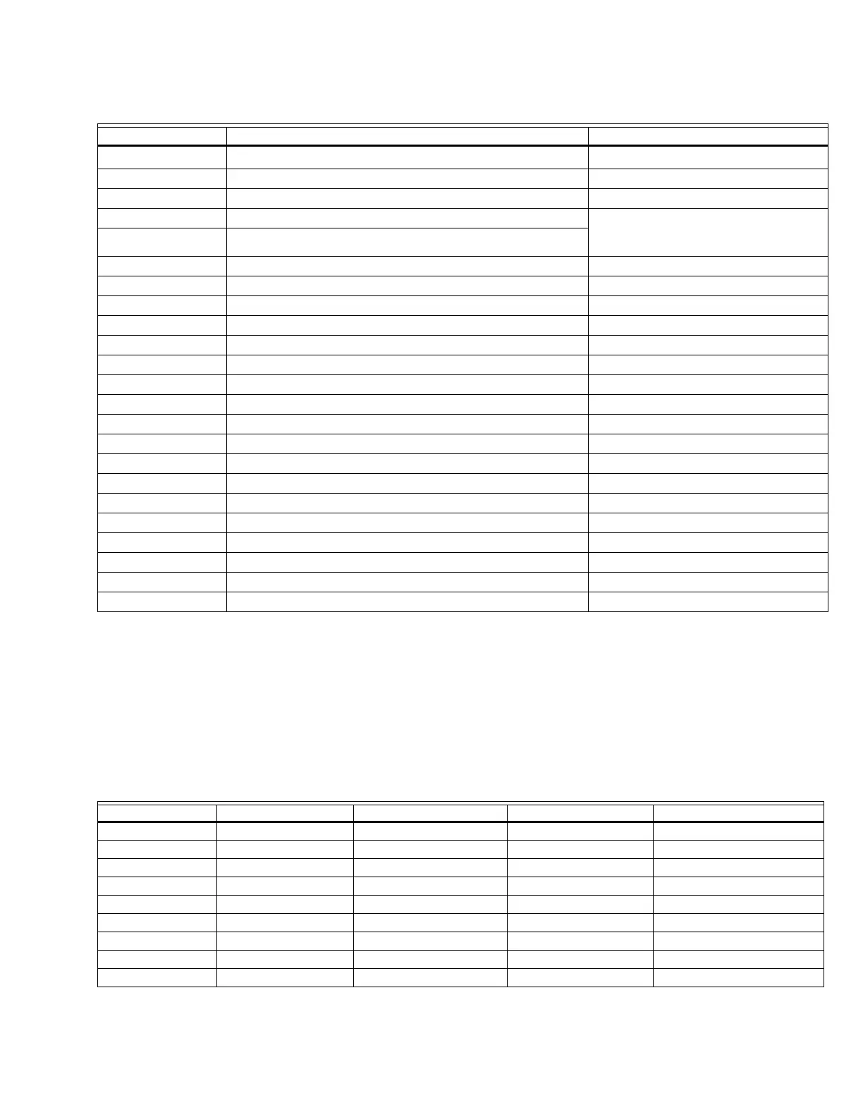
Table 1. Terminal Ratings.
Terminal No. Description Ratings (120 Vac)
G
Flame Sensor Ground
a
—
Earth G Earth Ground —
L2(N) Line Voltage Common —
3 Alarm 1A pilot duty
120 Vac (+10%/-15%),
50 or 60 Hz (±10%).
4
Line Voltage Supply (L1)
b
5 Burner Motor 9.8AFL, 58.ALR (inrush)
6 Burner Controller and Limits Demand (Not Valve Proving) 1 mA.
7 Lockout/Running Interlock 8A run, 43A inrush 8A run, 43A inrush
8 Pilot Valve/Ignition
c
9Main Fuel Valve
c
10 Ignition
c
F(11) Flame Sensor 60 to 220 Vac, current limited
12 Firing Rate High Fire 75VA pilot duty
13 Firing Rate Common 75VA pilot duty
14 Firing Rate Low Fire 75VA pilot duty
15 Firing Rate Modulate 75VA pilot duty
16 Valve Proving Switch 1 mA
17 Demand—Valve Proving 1 mA
18 Low Fire Switch Input 1 mA
19 High Fire Switch Input (7800/40L only) 1 mA
20 Pre-Ignition Interlock Input 1 mA
21 Interrupted First Stage Oil Valve or MV2
c
22 Shutter 0.5A
Table 2. Combinations for Terminals 8, 9, 10, and 21.
Combination No. Pilot Fuel # Main 9 Ignition 10 Valve 21
1 C F No load No load
2 B F No load No load
3 No load F No load B
4F F A No load
5No loadF A F
6D F A No load
7No loadD A D
8D D A No load
9No loadD A D