BNP
®
55 SUCTION BLAST CABINET Page 20
© 2019 CLEMCO INDUSTRIES CORP. www.clemcoindustries.com Manual No. 23350, Rev G, 02/19
7.6.5 Replace the frame in reverse order. Align the
top bolt holes with the bolts; slide the frame as
necessary.
7.6.6 Set the window squarely over the window
opening, making sure that all edges of the window are
centered and overlapping the window gasket, and that
the window is resting on the window support tabs.
7.6.7 Swing the window frame into place and tighten
the frame nuts.
7.7 LED Light Assembly
CAUTION
Use an approved stepladder when servicing the
light assembly. Do not climb on top of the
cabinet. The cabinet top will not support the
weight of a person. Failure can result in injury
and property damage.
7.7.1 Remove light-mount cover
7.7.1.1 Turn OFF electrical power.
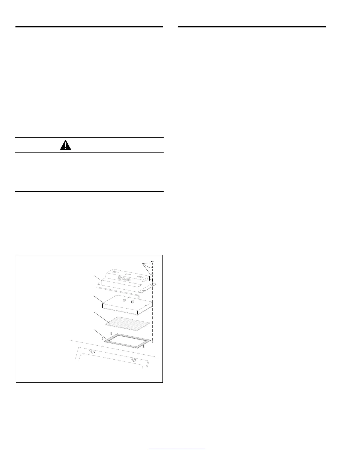
7.7.1.2 Remove the four nuts and washers that attach
the light-mount cover to the cabinet and remove the
cover, as shown in Figure 24.
Figure 24
7.7.2 Gasket replacement
7.7.2.1 Remove the four nuts and washers that attach
the light-mount cover to the cabinet and remove the
cover, as noted in Section 7.7.1. Move the light module
off the diffuser lens and remove the lens.
7.7.2.2 Remove all the old gasket material and clean
the surface of the cabinet.
7.7.2.3 Lay a section of strip gasket along the edge of the
opening and cut to length, allowing 3/4 overlap on each
end. Peel a short section of adhesive backing and adhere
the strip gasket to the top edge of the light opening, as
shown in Figure 24. Press the gasket to bond. Repeat the
process for each side, compressing the ends to seal.
7.7.3 Diffuser lens replacement
7.7.3.1 Remove the four nuts and washers that attach
the light-mount cover to the cabinet and remove the
cover, as noted in Section 7.7.1. Move the light module
off the diffuser lens and remove the lens. Inspect the
gasket and replace it, per Section 7.7.2, if it is
compressed or otherwise damaged, before centering
the new diffuser (smooth side up) over the gasket.
7.7.3.2 Set the light module on the diffuser and
reattach the cover.
7.7.4 LED light module replacement
7.7.4.1 Turn OFF electrical power and perform lockout
and tagout procedure to power supply.
7.7.4.2 Remove the light-mount cover, per Section 7.7.1.
7.7.4.3 Remove the junction-box cover and note the
wire connections. Current connections are as follows:
Brown wire .......................... Hot
Blue wire ............................. Neutral
Yellow w/green stripe ......... Ground
If color coding is different from that shown above, make
note of the color code before disconnecting the wires.
7.7.4.4 Loosen the strain-relief compression nut and
remove the cord from the junction box.
7.7.4.5 Place the new module in position on the
cabinet and route the cord through the strain relief and
into the junction box.
7.7.4.6 Cut the cord to length and wire as follows:
Brown wire .......................... Hot
Blue wire ............................. Neutral
Yellow w/green stripe ......... Ground
7.7.4.7 Apply power to test the light(s).
7.7.4.8 Tighten the strain-relief compression nut, set
the light module on the diffuser, and reattach the
cover.
LED Light-Mount Cover
Holds down the light module.
LED Light Module
Nut and Washers
Strip Gasket
Diffuser Lens
Smooth side up.