10 • OPACITY MONITOR MANUAL IM-A-08740-05 •
Wiring Tips
• Wire with extreme caution!
• All wiring must conform to the National Electrical Code and to local code regulations. Verify all electrical ratings
on equipment.
• Connecting high voltage to the low voltage circuits will damage the circuitry!
• Mount the display unit in such a manner that the wiring cable from the main electronics does not touch or ap-
proach any high magnetic source. If mounted near a high magnetic source, electronic interference may cause
the display to read incorrectly.
2.0 INSTALLATION
2.1 Mounting
Mount the electronics/display unit in a dry location where the ambient temperature is within the specied
temperature range, 32-160 ºF (0-70 ºC).
• Mount the unit away from excessive vibration.
• Do not mount in a wiring cabinet that has any power wiring in excess of 120 V ac.
• Mount the unit in such a manner that the wiring cable from the main electronics does not touch or approach
any high magnetic source. If mounted near a high magnetic source, electronic interference may cause the display
to read incorrectly.
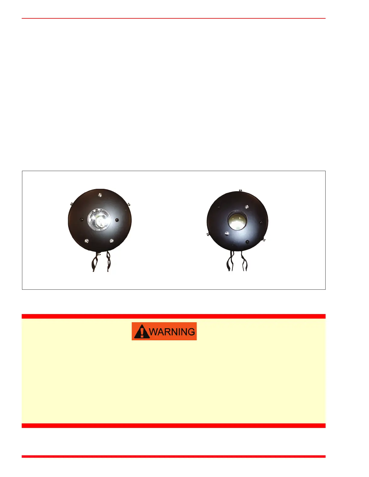
Referring to Figure 3, mount the LED light source and receiver units directly opposite each other on the
particulate passage. Select a position where a true, low-turbulence particulate sample is present, and where the
sight glasses are safely and conveniently accessible for cleaning. For applications where soot on the sight glass
might present a problem, apply purge air as shown in Figure 4 and Figure 5.
The width of the passage must not exceed 15 feet (4.57 meters). The length of the wires to the control unit
must not exceed 250 feet (76 meters).
Stack Units, left to right: P/N 31180 Light Source and P/N 31181 Receiver: These stack-mounted units are included with the base
electronics/display unit and two P/N 27367 Sight Glass Assemblies.
 Loading...