• OPACITY MONITOR MANUAL IM-A-08740-05 • 5
Table of Contents
Revision Control ................................................................................................................................................................... 2
Symbols Used in This Manual .............................................................................................................................................. 2
Safety Warnings .................................................................................................................................................................... 3
Wiring Tips ............................................................................................................................................................................ 3
Storage, Handling & Unpacking .......................................................................................................................................... 3
1.0 Introduction 7
1.1 Description of Operation ................................................................................................................................................ 7
1.2 Specications ................................................................................................................................................................ 8
1.3 Nomenclature.................................................................................................................................................................. 9
2.0 Installation 10
2.1 Mounting ....................................................................................................................................................................... 10
2.2 Wiring ............................................................................................................................................................................ 11
3.0 Operation & Maintenance 12
3.1 Displays and Indicators ................................................................................................................................................ 12
3.2 Field Conguration on Continuous Display Screen ................................................................................................... 12
3.3 Calibration on Continuous Display Screen ................................................................................................................. 13
3.4 Other Adjustments on Continuous Display Screen ................................................................................................... 13
4.0 Miscellaneous 14
4.1 Retransmission of Process Variable ........................................................................................................................... 14
4.2 Modbus Communications ............................................................................................................................................ 14
4.3 Troubleshooting (Diagnostic LED’s) ............................................................................................................................ 14
5.0 Customer Service Information 15
5.1 Contacts ........................................................................................................................................................................ 15
5.2 Repairs .......................................................................................................................................................................... 15
5.3 Service .......................................................................................................................................................................... 15
5.4 Standard Terms and Conditions of Sale...................................................................................................................... 16
6. Appendices: Drawings & Tables 17
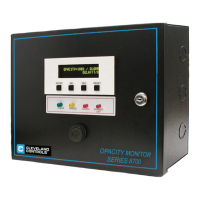
Photo 1 (Front Cover): Electronics/Display Assembly ....................................................................................................... 2
Photo 2: Optional Separate Purchase: P/N 31726 Purge Air Blower Kit ........................................................................... 7
Photo 3: Stack Units, left to right: P/N 31180 Light Source and P/N 31181 Receiver .................................................... 10
Figure 1: Printed Circuit Board Assembly for A-08740 Universal Opacity Monitor. ..................................................... 18
Figure 2: Housing Dimensions for A-08740 Universal Opacity Monitor. ........................................................................ 19
Figure 3: Mounting the Breeching Units (A-08740 Universal Opacity Monitor). ........................................................... 20
Figure 4: Typical Air Supply Arrangement for Sight Glass Purge ................................................................................... 21
Figure 5: Typical Air Supply Arrangement for Sight Glass Purge with Blower (P/N 31726). ........................................ 22
Figure 6: Field Wiring for Universal Opacity Monitor, basic model (no auxiliary modules). ......................................... 23
Figure 7: Field Wiring for Universal Opacity Monitor Equipped with NYC Burner Cutoff Module. .............................. 24
Figure 8: Field Wiring for Universal Opacity Monitor Equipped with Overre Air Timer Module. ............................... 25
Figure 9: Field Wiring for Universal Opacity Monitor Equipped with Purge Air Blower System. ................................. 26
Figure 10: Summary of Continuous Display Screen ........................................................................................................ 27
Figure 11a: Scrolling Display Screens for Standard Models A-08740-A0-0X (1a through 5) ....................................... 28
Figure 11b: Scrolling Display Screens for Standard Models A-08740-A0-0X (6 through 10d) ..................................... 29
Figure 11c: Scrolling Display Screens for Standard Models A-08740-A0-0X (11a through 13) ................................... 30
Figure 12a: Scrolling Display Screens for Standard Models A-08740-A0-1X (1a through 5) ....................................... 31
Figure 12b: Scrolling Display Screens for Standard Models A-08740-A0-1X (6 through 10d) ..................................... 32
Figure 12c: Scrolling Display Screens for Standard Models A-08740-A0-1X (11a through 13) ................................... 33
Figure 13a: Scrolling Display Screens for Standard Models A-08740-A0-2X (1a through 5) ....................................... 34
Figure 13b: Scrolling Display Screens for Standard Models A-08740-A0-2X (6 through 10d) ..................................... 35
Figure 13c: Scrolling Display Screens for Standard Models A-08740-A0-2X (11a through 13) ................................... 36
Figure 14: Modbus Memory Addresses ........................................................................................................................... 37
Figure 15: “Processor Running” LED ............................................................................................................................... 37
Figure 16: Troubleshooting ................................................................................................................................................ 38

 Loading...